How does encoding work in digital audio? Part 3

The structure of the digital audio path.

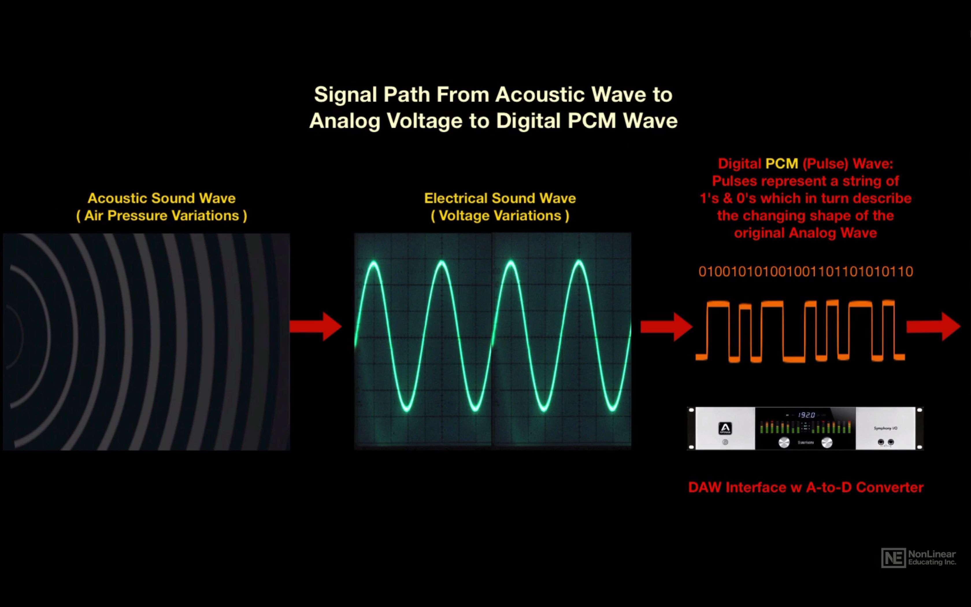
When playing music, something like the following happens: the player, using a codec created in the form of a device or program, decompresses the file into a specific format (FLAC, MP3 and others) or reads data from a CD, DVD-Audio or disc SACD, receiving a standard PCM data stream … This sequence is then sent via USB, LAN, S / PDIF, PCI, etc. to the I2S converter. In turn, the converter converts the received data into so-called I2S data interface frames (not to be confused with I2C!).
I2S
I2S is a digital audio transmission serial bus. Now I2S is a standard for connecting a signal source (computer, turntable) to a digital-to-analog converter. It is through it that the vast majority of the DAC connects directly or indirectly. There are other digital audio transmission standards, but they are much less common.
I2S output (input) on PCB
I2S output (input) on PCB
Other articles in this issue:
Xakep # 256. Fight Linux
Problem content
Subscription to “Hacker”
The I2S bus can consist of three, four, or even five pins:
continuous serial clock (SCK) – bit sync clock (can be called BCK or BCLK);
word selection (WS) – frame sync clock (may be called LRCK or FSYNC);
serial data (SD): the signal of the transmitted data (can be called DATA, SDOUT or SDATA). As a general rule, data is transmitted from a transmitter to a receiver, but there are devices that can act as a receiver and transmitter at the same time. In this case, another contact may be present;
Serial data in (SDIN): On this pin, data moves in the receive direction, not transmit.
SD or SDOUT is used to connect a D / A converter and SDIN is used to connect an A / D converter to the I2S bus.
In most cases, there is another pin, the master clock (MCLK or MCK), which is used to synchronize the transmitter and receiver from the same clock to reduce the transmission error rate. For external synchronization of MCLK, two clock generators are used: with a frequency of 22 579 kHz and 24 576 kHz. The first, 22,579 kHz, is for frequencies that are multiples of 44.1 kHz (88.2, 176.4, 352.8 kHz), and the second, 24,576 kHz, is for frequencies that are multiples of 48 kHz (96, 192, 384 kHz). There may also be generators at 45158.4 kHz and 49152 kHz; You’ve probably already noticed how in the world of digital sound they like to double everything.
Frame or I2S frame
In I2S, three contacts are necessarily used: SCK, WS, SD; all other contacts are optional.
On the SCK channel, synchronization pulses are transmitted, under which the frames are synchronized.
The length of the “word” is transmitted over the WS channel and logical states are also used. If the WS pin is a logical unit, then the right channel data is transmitted, if it is zero, the left channel data.
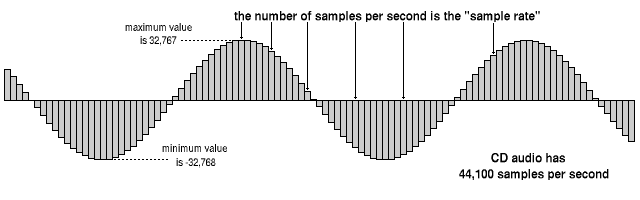
The data bits are transmitted via SD: the amplitude values of the audio signal during quantization, the same 16, 24 or 32 bits. No checksums or service channels are provided on the I2S bus. If the data is lost in transit, there is no way to get it back.
Expensive DACs often have external connectors to connect to I2S. The use of such connectors and cables can have a negative effect on the sound, even the appearance of “artifacts” and stuttering, everything will depend on the quality and length of the cable. Still, I2S is a plug-and-play connector, and the length of the wires from the transmitter to the receiver should tend to zero.
Let’s take a look at how the PCM data stream is transmitted over the I2S bus. For example, when transmitting PCM 44.1 kHz at 16 bits, the length of the word on the SD channel will be these sixteen bits and the length of the frame will be 32 bits (right + left). But most of the time, the transmitters use a 24-bit word length.