How digital compression works. Part 4


Free Download Mp4Gain
picture

How digital compression works. Part 4

AUDIO COMPRESSION

Record labels are good too: contrary to what music lovers expected, they didn’t take full advantage of the new high-definition format. The studios did not record music from the master tape in DSD, instead taking a digital recording in PCM, remixing and processing everything in a row: limiters, compressors, noise-shaping dithering, and various digital filters. The result was a sound so sterile and dry that even CD Audio could have sounded much better. In this way, listeners’ trust in SACD and, at the same time, in new formats in general was undermined.

DIGITAL COMPRESSION

INFO
Unfortunately, with vinyl records, this vicious practice continues to this day: studios print vinyl from a digital recording, even if they have the recording on the master tape. So on modern vinyl it can easily be 44.1 x 16.

DSD
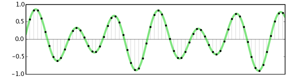
What is DSD? This is a one-bit stream with a very high sample rate compared to PCM. Also, DSD uses a different type of modulation, PDM (Pulse Density Modulation) – pulse density modulation. Sound recording in this format is done by a one-bit analog-to-digital converter, now these ADCs based on sigma-delta modulation are used everywhere. The recording process looks like this: while the amplitude of the wave increases, the ADC output is a logical unit, when the amplitude decreases, the output is a logical zero, there can be no average value. It is compared with the previous value of the wave amplitude.

DSD achieves significant advantages over PCM:

more precisely, draw a wave;
greater immunity to noise;
an easier way to switch and transmit a digital stream;
In theory, it is possible to reduce the cost by simplifying the DAC circuit, but due to backward compatibility, manufacturers are unlikely to accept it.
Originally, SACDs used the DSD x64 format with a sample rate of 2822.4 kHz. The 44.1 kHz audio CD sample rate was taken as the basis, increased 64 times, hence the name x64. The following DSDs are currently in use:

x64 = 2822.4 kHz;
x128 = 5644.8 kHz;
x256 = 11 289.6 kHz;
x512 = 22,579.2 kHz;
declared DSD x1024.

DXD
There is a certain intermediate format between PCM and DSD called DXD – Digital eXtreme Definition. This is, in fact, high definition PCM: 352.8 kHz or 384 kHz with 24 or 32 bit quantization. It is used in studies for the processing and subsequent mixing of materials.

But this approach is flawed: first, it doesn’t allow you to use all the benefits of DSD, and second, the file size is larger than DSD. Currently, flagship DACs on the I2S input accept a PCM data stream with a sample rate of up to 768 kHz and a bit depth of up to 32 bits. It’s scary to even consider how much hard drive space an album will take up at this resolution.

DSD has practically separated from SACD. Now, the DSD format can often be found packaged in files with the DSF and DFF extensions. Many turntables have been released with the ability to record in DSF and DFF, lovers of good sound are increasingly digitizing vinyl records in DSD format. But in recording studios, nobody wants to invest in unpopular formats, so they continue to rivet the sound with minimum wages: 44.1 × 16.

DSD switching and data transmission
To transfer a digital stream to DSD, a three-pin connection scheme is used:

DSD clock pin (DCLK) – sync;
Data input pin DSD Lch (DSDL) – left channel data;
Data input pin DSD Rch (DSDR): right channel data.

Unlike I2S, DSD data transmission is extremely simplified. DCLK sets the clock rate of the bit sync, and the left and right channel data is transmitted sequentially through the DSDL and DSDR pins, respectively. Here there are no adjustments, recording and playback in DSD is done little by little. This approach provides the closest approximation to the analog signal, and due to the high frequency, quantization noise is reduced and reproduction precision is increased by an order of magnitude.

PDO
DoP is often used to carry DSD data streams, so it is worth mentioning. DoP is an open standard for transferring DSD data over PCM frames (DSD over PCM). The standard was created to pass a stream through controllers and devices that do not support direct DSD streaming (not DSD native).

The principle of operation is as follows: in a 24-bit PCM frame, the upper 8 bits are padded with ones; this means that DSD data is currently being transmitted. The remaining 16 bits are sequentially filled with DSD data bits.


Free Download Mp4Gain
picture


Mp4Gain Main Window
picture


Mp4Gain Features
picture


Free Download Mp4Gain
picture

How digital compression works. Part 3

How digital compression works. Part 3

DIGITAL COMPRESSION

In most cases, there is another pin, Master Clock (MCLK or MCK), which is used to synchronize the transmitter and receiver from the same clock to reduce the transmission error rate.

DIGITAL COMPRESSION

For the external synchronization of the MCLK, two clock generators are used: with a frequency of 22 579 kHz and 24 576 kHz. The first, 22,579 kHz, is for frequencies that are multiples of 44.1 kHz (88.2, 176.4, 352.8 kHz), and the second, 24,576 kHz, is for frequencies that are multiples of 48 kHz (96, 192, 384 kHz). There may also be generators at 45,158.4 kHz and 49,152 kHz; You’ve probably already noticed how in the digital sound world they like to multiply everything by two.

Frame or I2S frame
Frame or I2S frame
In I2S, three contacts are necessarily used: SCK, WS, SD; the rest of the contacts are optional.

Synchronization pulses are transmitted through the SCK channel, under which the frames are synchronized.

The length of the “word” is transmitted over the WS channel and logical states are also used. If the WS pin is a logical unit, then the right channel data is transmitted, if it is zero, the left channel data is transmitted.

The data bits are transmitted via SD: the values ​​of the amplitude of the audio signal during quantization, the same 16, 24 or 32 bits. No checksums or service channels are provided on the I2S bus. If data is lost in transit, there is no way to get it back.

Expensive DACs often have external connectors to connect to the I2S. The use of such connectors and cables can have a bad effect on the sound, even the appearance of “artifacts” and stuttering, everything will depend on the quality and length of the cable. Still, I2S is a hard-wired connector and the length of the wires from the transmitter to the receiver should tend to zero.

Let’s see how the PCM data stream is transmitted through the I2S bus. For example, when transmitting PCM 44.1 kHz at 16 bits, the length of the word on the SD channel will be these sixteen bits and the length of the frame will be 32 bits (right + left). But most of the time, the transmitters use a 24-bit word length.

When playing PCM 44.1×16, the most significant bits are simply ignored as they are filled with zeros or, in the case of older multi-bit DACs, they can go to the next frame. The length of the “word” (WS) may also depend on the player through which the music is played, as well as the driver for the playback device.

An alternative to PCM and I2S would be to record the audio signal in DSD. This format was developed in parallel with PCM, although Kotelnikov’s theorem also played a role here. To improve sound quality compared to CDDA, the emphasis was not on increasing the quantization bit, as in the DVD Audio format, but on increasing the sample rate.

DSD
DSD stands for Direct Stream Digital. It originates from Sony and Philips labs, however, just like the other formats discussed in this article.

SACD
DSD first saw the light of day on Super Audio CDs in 2002.

At the time, SACD seemed like a masterpiece of engineering, it applied a completely new way of recording and playback, very close to analog devices. The implementation was simple and elegant at the same time.

The media was even equipped with copy protection, although without it, no pirate was afraid. Under the Sony and Philips brands, they began to produce “closed” devices exclusively for playback, with no possibility of copying discs. Manufacturers sold recording equipment to studios, but kept control over the SACD launch.

Who knows, perhaps the SACD format could gain popularity comparable to Audio CD, if it weren’t for the cost of the playback devices. By unreasonably selling out player prices, Sony and Philips’ own leaders hampered the popularity of their format. And the next mistake completely put an end to the sale of specialized devices. To promote Sony’s PlayStation, Sony engineers have added the ability to listen to SACD on it. Hackers immediately hacked the set-top box and began copying SACD discs into ISO images that can be burned to a regular DVD and played on any competing player; others simply ripped out tracks to play on a computer.

How digital compression works. Part 2

How digital compression works. Part 2

digital compression

The next after CDDA in 1987 appeared the DAT format – Digital Audio Tape.

digital compression

The sample rate was 48 kHz, the quantization bit did not change. And although the format failed, the 48 kHz sample rate took hold in recording studios, as they say, due to the convenience of digital processing.

In 1999, the DVD-Audio format was released, which made it possible to record on a disc six stereo tracks with a sampling frequency of 96 kHz and a 24-bit bit depth, or two stereo tracks with a frequency of 192 kHz, 24 bits.

In the same year, the SACD – Super Audio CD format was introduced, but the discs began to be produced only three years later. I will tell you more about this format in the DSD section.

These are the main formats that are considered the standard for digital audio recordings on media. Now let’s see how data is transmitted on a digital audio path.

The structure of the digital audio path.
When playing music, something like the following happens: the player, using a codec created in the form of a device or program, decompresses the file into a specific format (FLAC, MP3 and others) or reads data from a CD, DVD-Audio or disc SACD, receiving a standard PCM data stream … This stream is then transferred via USB, LAN, S / PDIF, PCI, etc., to the I2S converter. In turn, the converter converts the received data into so-called I2S data interface frames (not to be confused with I2C!)

I2S
I2S is a digital audio transmission serial bus. Now I2S is a standard for connecting a signal source (computer, turntable) to a digital-to-analog converter. It is through it that the vast majority of the DAC connects directly or indirectly. There are other digital audio transmission standards, but they are much less common.

I2S output (input) on PCB
Other articles in this issue:
Xakep # 256. Fight Linux
Broadcast content
Subscription to “Hacker”
The I2S bus can consist of three, four, or even five pins:

continuous serial clock (SCK) – bit sync clock (can be called BCK or BCLK);
word selection (WS) – frame sync clock (may be called LRCK or FSYNC);
Serial data (SD): transmitted data signal (can be called DATA, SDOUT, or SDATA). As a general rule, data is transmitted from a transmitter to a receiver, but there are devices that can act as a receiver and transmitter at the same time. In this case, another contact may be present;
Serial data in (SDIN): On this pin, data moves in the receive direction, not the transmit direction.
SD or SDOUT is used to connect a D / A converter, and SDIN is used to connect an A / D converter to the I2S bus.

How digital compression works.

How digital compression works.

Digital Compression

Have you ever wondered how sound is reproduced on digital devices?

Digital Compression

How is a sound signal formed from a combination of ones and zeros? I’m sure I was thinking, since I started reading! But often, even professionals only have a general idea of ​​the modern sound route. In this article, you will learn how the different formats appeared, what a digital-to-analog converter is, what types of DACs exist, and what determines the quality of sound reproduction.

PCM
As you know, in digital audio, almost any format, with rare exceptions, is recorded using a pulse code stream or a PCM stream – pulse code modulation. FLAC, MP3, WAV, Audio CD, DVD-Audio and other formats are just ways to package, “preserve” a PCM stream.

How it all began
The theoretical foundations of digital sound transmission were developed at the dawn of the 20th century, when scientists tried to transmit an audio signal over a long distance, but not by telephone, but in a rather strange way for that time.

By dividing the sound wave into small parts, it could be sent to the receiver in some kind of mathematical representation. The recipient, in turn, could restore the original waveform and listen to the recording. In addition, scientists were faced with the task of increasing the bandwidth of the “ether”.

In 1933, the theorem of V.A. Kotelnikov. In Western sources, it is called the Nyquist-Shannon theorem. Yes, Harry Nyquist was the first to raise this issue: in 1927 he calculated the minimum sampling frequency to transmit a waveform, which later got his name “Nyquist frequency”, but Kotelnikov’s theorem was published 16 years ago before.

The essence of the theorem is simple: a continuous signal can be represented as an interpolation series consisting of discrete reports, from which the signal can be reconstructed. In order to roughly restore the original state of the signal, the sampling frequency must be at least twice the upper cutoff frequency of this signal.

For many years, the theorem was not in demand, until the advent of the digital age. It was then that it found a use. In particular, the theorem was useful when developing the CDDA (Compact Disc Digital Audio) format, in common people it is called Audio CD or Red Book. The format was released by engineers at Philips and Sony in 1980 and became the standard for audio CDs.

Format characteristics:

sampling frequency – 44.1 kHz;
quantization capacity – 16 bits.

INFO
The sampling rate is the number of signal samples taken during your sampling. Measured in Hertz.
Quantization bit: the number of binary bits that express the amplitude of the signal. Measured in bits.
The 44.1 kHz sampling frequency was calculated from Kotelnikov’s theorem. It is believed that the hearing of the average person cannot pick up sound beyond 19-22 kHz. The frequency was probably 22 kHz and was chosen as the upper limit.

22,000 × 2 = 44,000 + 100 = 44,100 Hertz

Where does 100 Hertz come from? There is a version that this is a small margin in case of errors or oversampling. In fact, Sony chose this frequency for its compatibility with the PAL transmission standard.

The bit depth of the CDDA format is 16 bits, or 65,536 samples, which equates to a dynamic range of approximately 96 dB. Such a large number of samples were not chosen by chance. Firstly, due to the strong influence of quantization noise, and secondly, to provide a formal dynamic range superior to that of the main competitors at the time – cassette records and vinyl records. I’ll cover this in more detail in the section on digital to analog converters.

The development of PCM continued on the principle of multiplying by two. Other sample rates appeared: first, the 48 kHz sample rate was added, and then the frequencies based on it were 96, 192, and 384 kHz. The 44.1 kHz frequency was also doubled to 88.2, 176.4, and 352.8 kHz. Bit depth increased from 16 to 24 and then to 32 bits.

Audio encoding: secrets revealed

Audio encoding: secrets revealed

Digital Audio

Audio settings for video capture and transmission.

Digital Audio

As people directly related to the AV sphere, we constantly talk about audio coding and audio codecs, but what is it? An audio codec is essentially a device or algorithm that can encode and decode a digital audio signal.

In practice, the audio waves that travel through the air are continuous analog signals. The signals are converted to digital form by a device called an analog-to-digital converter (ADC), and the reverse converter is called a digital-to-analog converter (DAC). The codec lies between these two functions and it is he who allows you to adjust some important parameters for the successful capture, recording and transmission of an audio signal: the codec algorithm, the sampling frequency, the bit width and the speed of the audio signal. data.

The three most popular audio codecs are Pulse-Code Modulation (PCM), MP3, and Advanced Audio Coding (AAC). The choice of codec determines the compression rate and the recording quality. PCM is a codec used by computers, CDs, digital phones, and sometimes SACD. The PCM signal source is sampled at regular intervals, and each sample is the digital amplitude of the analog signal. PCM is the simplest option for digitizing an analog signal.

With the correct parameters, this digitized signal can be fully converted to analog without any loss. But this codec, which provides almost complete identity with the original audio, is unfortunately not very cheap, which results in large files, and these files are not suitable for streaming. We recommend using PCM to record digital images for your sources or when doing audio post-processing.

Fortunately, we always have the option of choosing a different codec that can compress digital data (versus PCM) based on some helpful observations on the behavior of sound waves. But in this case, you have to make a compromise: all alternative algorithms are associated with “losses”, since it is impossible to completely restore the original signal, but nevertheless the result is still so good that most users will not be able to to catch the difference.

MP3 is an audio encoding format that uses a digital data compression algorithm that allows you to save the audio signal in smaller files. The MP3 codec is the most used by users to record and store music files. We recommend using MP3 to stream audio content as it requires less network bandwidth.

AAC is a newer audio encoding algorithm that is the successor to MP3. AAC has become the standard for MPEG-2 and MPEG-4 formats. In fact, this is also a digital data compression codec, but with less quality loss than MP3 when encoded with the same bit rate. We recommend using this codec for online streaming.

Sampling frequency (kHz, kHz)
Sample rate (or sample rate): the frequency with which the signal is digitized, stored, processed or converted from analog to digital. Time sampling means that the signal is represented by several of its samples (samples) taken at regular intervals.

Measured in hertz (Hz, Hz) or kilohertz (kHz, kHz,) 1 kHz equals 1000 Hz. For example, 44,100 samples per second can be labeled 44,100 Hz or 44.1 kHz. The selected sample rate will determine the maximum playback frequency and, as follows from Kotelnikov’s theorem, to fully restore the original signal, the sample rate must be twice the highest frequency in the signal spectrum.

As you know, the human ear is capable of picking up frequencies between 20 Hz and 20 kHz. Given these parameters and the values ​​shown in the following table, you can understand why 44.1 kHz was chosen as the sampling frequency for CD and is still considered a very good frequency for recording.

What are the problems with digital audio?

What are the problems with digital audio?

digital audio

As with many areas of technology, there is no single standard for digital audio.

DIGITAL AUDIO

It can be presented in various standards: AES / EBU 110 Ohm, AES-ID3 75 Ohm, S / PDIF 75 Ohm, Optical Toslink, among others. The sampling frequency can be from 32 kHz to 192 kHz with different bit depths. To work with all the variety of standards in a serious studio, you need to have an interface unit, better a digital audio converter or a sample rate converter.

What are the problems with digital video?
Digital video (SDI) is similar in some respects to analog video. In it, the quality of the cables and connectors is also important for normal operation, the loss of high frequencies of the signal in them also affects the quality of the signal. Due to many factors that affect the analog signal, fluctuations can appear in digital systems, at a certain level of which there is a complete blockage of the image (clipping effect *). A little lost in digital video can have far more serious consequences than a pixel lost in analog. When working with digital video, restoration of signal quality (equalization of the frequency spectrum and restoration of clock frequency) is often required. The format (“language”) of a digital signal is very important for its correct transmission, since the transmission protocols are very specific.
Level incompatibility is a rare problem in analog technology. Digital signals, however, can have different and incompatible levels: TTL, ECL or others. Another problem with digital signals is the adaptation of the load capacity of the digital inputs and outputs, which must also be addressed.

What is the easiest way to input a digital video signal into a computer?
The easiest and cheapest way is to use a DV video source and a Firewire® card on your computer (or the built-in interface on many modern computers). The entry procedure is simple and fast. For analog video, you can use an analog video capture card or an external analog video to DV converter connected to the Firewire® card.

Why do I sometimes have difficulties with the DV format?
The digital video format that uses a DV or mini-DV cassette and Firewire® technology has a very high bit rate, which limits the length of the connecting cable. Attempting to use long cables will cause many bit stream problems, such as clipping effect * when the image is completely lost. Another problem is a consequence of two-way communication between devices connected via Firewire® and manifests itself when trying to randomly connect multiple DV devices.

What is a device for embedding (extracting) digital audio into an SDI signal?
The total digital stream of digital serial video can include multiple channels of digital audio. An SDI embedder is used to insert digital audio into an SDI signal, and an SDI embedder is used to extract digital audio from a mixed stream.

Audio. Digital and Analog Audio Part 6

Audio. Digital and Analog Audio Part 6

Digital Audio

ANALOG AUDIO PROCESSING

digital audio

Any processing of an analog audio signal is accompanied by a certain loss of its quality (frequency, phase, non-linear distortions occur), but it is necessary. The main types of processing are as follows:

amplification of the signal to the level required for transmission, recording or playback through the speaker: having sent the signal from the microphone to the speaker, we will not hear anything: it is necessary to pre-amplify it in terms of level and power, while providing the ability to adjust the volume.

frequency filtering: infrasound, which is harmful to health at certain frequencies, and ultrasounds are cut off from the useful sound range (20 Hz – 20 kHz). In many cases, the range is deliberately reduced (the voice phone channel has a band from 300 Hz to 3400 Hz, the frequency band of metered radio stations is significantly limited). For loudspeaker systems, which usually have 2-3 bands, separation is also necessary, which is usually carried out in the crossover filters already at the level of the amplified (powerful) signal.

frequency correction (equalization): tone control, compensation for uneven recoil due to acoustic properties of the room, compensation for losses in transmission lines, studio processing to achieve the desired “color” of sound, suppression of feedback parasitic acoustics (“whistle”), etc., etc.

Noise suppression: there are special dynamic noise reduction schemes that analyze the signal and reduce the bandwidth in proportion to the level and frequency of the RF components (“denoisers”, “dehissers”). In this case, the noise that is above the bandwidth of the signal is cut off and the remaining noise is more or less masked by the signal itself. Such schemes always lead to a very noticeable degradation of the signal, but in some cases their use is appropriate (for example, when working with a recorded speech or on intercom radio stations). For analog sound recording equipment, compressor / expander-based noise cancellers (“compander” eg Dolby B, dbx systems) are also used, the work of which is less perceptible to the ear.
Impact on dynamic range: In order to make the playback of music programs in ordinary home systems, including car radio, rich and expressive enough, the dynamic range is compressed, making the sound of quiet sounds more strong. Otherwise, in addition to the occasional bursts of fortissimo (in classical music), you will have to listen to the silence from the speakers, especially given the noisy environment. For this, devices called compressors are used. In some cases, on the contrary, it is required to expand the dynamic range, then expanders are used. And to exclude exceeding the maximum level, which will lead to clipping (limiting the signal from above, accompanied by very high non-linear distortions, perceived as wheezing), limiters are used in studies.

special effects for studios, EMP, etc.: available to sound engineers and musicians there is a large number of special equipment to give the sound the desired color or to obtain a specific effect. These are various distorters (the sound of an electric guitar becomes hoarse, grainy), wah-wah prefixes (amplitude modulation that causes a characteristic “croaking” effect), enhancers, and exciters (devices that affect the color of the sound, in In particular, it can give the sound a “tube” tint); flangers, choruses, etc.

sound mixing, echo / reverb: recording in studios is usually done in multi-channel form, then, using mixers, the phonogram is reduced to the required number of channels (usually 2 or 6). In this case, the sound engineer can “push forward” one or another solo instrument recorded on a separate track, changing the loudness ratio of different tracks. Sometimes multiple copies of a lower level are superimposed on the signal with a certain time shift, thus simulating natural reverb (echo). Currently, similar and other effects are mainly achieved using signal processors that process digital signals.

Audio. Digital and Analog Audio Part 5

Audio. Digital and Analog Audio Part 5

Digital Audio

Any amplification path is non-linear, so harmonic distortion always occurs – new frequency components spaced 3, 5, 7, etc. in frequency. of the tone that generates them (odd harmonics) or in 2, 4, 6, etc. times (even).

Digital Audio


The threshold of visibility of harmonic distortions varies widely: from a few tenths or even hundredths of a percentage to 3-7%, depending on the composition of the harmonics. Even the harmonics are less noticeable, since they are in line with the fundamental tone (the difference in frequency is twice corresponding to one octave).

In addition to harmonic distortions, intermodulation distortions occur, which are the differential products of the frequencies of the signal spectrum and its harmonics. For example, at the output of an amplifier, at the input of which two frequencies of 8 and 9 Hz are applied (with a sufficiently non-linear characteristic), a third (1 kHz) will appear, as well as several others: 2 kHz (as the difference of the second harmonics of the fundamental frequencies), etc. … Intermodulation distortion is especially annoying to the ear, as it generates many new sounds, including those that are dissonant to the main ones.

What an audiophile can hear, and not only hear, but also explain to a sound engineer, can be completely invisible to the average listener.

Noise and distortion are largely masked by the signal, but they themselves mask low-level signals that fade or lose clarity. Therefore, the higher the signal-to-noise ratio, the better. Actual sensitivity to noise and distortion will vary based on individual hearing characteristics and training. The level of noise and distortion that does not affect the transmission of speech can be completely unacceptable for music. What an audiophile can hear, and not only hear, but also explain to a sound engineer, can be completely invisible to the average listener.

ANALOGUE AUDIO TRANSFER
Traditionally, audio signals were transmitted over cables and over the air (radio).

Distinguish between unbalanced (classic cable) and balanced transmission line. Unbalanced has two wires: signal (direct) and return (ground). Such a line is very sensitive to external interference, so it is not suitable for transmitting a signal over long distances. Often implemented with a shielded cable, the shield is grounded.

cifrovoe-i-analogovoe-audio-4.jpg
FIG. 4. Unbalanced screened line

The balanced line assumes three wires: two signal wires, through which the same signal flows, but in antiphase, and ground. On the receiving side, the common mode noise (induced in both signal wires) is mutually subtracted and completely disappears, and the useful signal level is doubled.

FIG. 5. Balanced screened line

Unbalanced lines are often used inside devices and for short distances, mainly on user routes. In the professional sphere, balance prevails.

In the figures, the shield connection points are shown conditionally, as they must be selected “in place” each time to achieve the best results. Most of the time, the screen is connected only on the signal receiver side.

Audio. Digital and analog audio Part 3

Audio. Digital and analog audio Part 3

DIGITAL AUDIO

Modern autumn sound sources are diverse and digital media are becoming more and more common: CDs, DVDs, although vinyl records are also preserved. We continue to listen to radio, both terrestrial and via cable (radio hotspots). Sound accompanies television shows and movies, not to mention such a familiar phenomenon as telephony.

Digital Audio


A computer receives an increasing share in the world of audio, allowing it to conveniently archive, combine and process sound programs in the form of files. In the digital age, digitized speech and music are transmitted through digital channels, including the Internet, without serious losses in transportation. This is done with digital encoding and the loss is due solely to compression, which is used most often. However, in digital media, either it does not exist at all (CD, SACD), or lossless audio compression algorithms are used (DVD Audio, DVD Video). In other cases, the degree of compression is determined by the required level of quality of the soundtrack (MP3 files, digital telephony, digital television, some types of media).

cifrovoe-i-analogovoe-audio-1.jpg
FIG. 1. Conversion of acoustic sound vibrations into an electrical signal

The reverse conversion of electrical vibrations to acoustic vibrations is carried out using speakers built into radios and televisions, as well as separate acoustic systems, headphones.

Sound is called acoustic vibrations in the frequency range 16 Hz to 20,000 Hz.

Sound is called acoustic vibrations in the frequency range 16 Hz to 20,000 Hz. Below (infrasound) and above (ultrasound), the human ear does not hear, and within the sound range, the sensitivity of hearing is very uneven. , its maximum falls at a frequency of 4 kHz. To hear sounds of all frequencies at the same volume, you must play them at different levels. This technique, called loudness, is often implemented in home computers, although its result cannot be considered unequivocally positive.

cifrovoe-i-analogovoe-audio-2.jpg
FIG. 2. Equal volume curves
(Click on the image to zoom)

The physical properties of sound are generally not presented in linear values, but in relative logarithmic values, decibels (dB), as this is much clearer in numbers and more compact in graphics (otherwise one would have to operate with values ​​that they have many zeros before and after the decimal point, and the second would be easily lost in the context of the first). The ratio of two levels A and B in dB (say voltage or current) is defined as:

With u [dB] = 20 lg A / B. If we talk about powers, then C p [dB] = 10 lg A / B.

In addition to the frequency range, which determines the human ear’s sensitivity to tone, there is also the concept of loudness range, which shows the ear’s sensitivity to loudness level and covers the range from the lowest audible sound to the ear (threshold sensitivity) to the strongest, beyond which is the pain threshold. The sensitivity threshold is taken as a sound pressure of 2 x 10⁻⁵Pa (Pascal), and the pain threshold is pressure, 10 million times higher. In other words, the audibility range, or the pressure ratio between the loudest and the lowest sound, is 140 dB, which is markedly higher than the capabilities of any audio equipment due to its own noise. Only high definition digital formats (SACD, DVD Audio) match the theoretical limit of dynamic range (the ratio of the loudest sound reproduced by the equipment to the noise level) 120 dB, CD provides 90 dB, vinyl record – approximately 60 dB.

cifrovoe-i-analogovoe-audio-3.jpg
FIG. 3. Hearing sensitivity range

Only high definition digital formats (SACD, DVD Audio) match the theoretical dynamic range limit

Noise is always present in the audio path. This is both the intrinsic noise of the amplifying elements and the external interference. Signal distortions are divided into linear (amplitude, phase) and non-linear or harmonic. In the case of linear distortion, the signal spectrum is not enriched with new components (harmonics), only the level or phase of the existing ones changes. Amplitude distortions that violate the original level relationships at different frequencies result in audible timbre distortions. For a long time it was believed that phase distortions were not critical to hearing, but today the opposite has been shown: both timbre and sound localization are highly dependent on the phase relationships of the signal’s frequency components. .

Audio. Digital and analog audio

Audio. Digital and analog audio

Digital Audio

Although we assimilate most of the external information with the help of our eyes, sound images are no less important to us and often even more.

Digital Audio

Try watching a movie with the sound turned off; in 2-3 minutes you will lose the thread of the plot and the interest in what is happening, no matter how big the screen and the high quality image. Therefore, a pianist played off-screen in silent movies. If you remove the picture and leave the sound, the movie can be “heard” like a fascinating radio show.

Hearing gives us information about what we do not see, since the sector of visual perception is limited, and the ear captures the sounds that come from everywhere, complementing the visual images.

Hearing gives us information about what we do not see, since the visual perception sector is limited, and the ear captures sounds from all directions, complementing visual images. At the same time, our hearing with great precision can locate an invisible sound source in direction, distance, speed of movement.

They learned to convert sound into electrical vibrations long before images. This was preceded by a mechanical recording of sound vibrations, whose history dates back to the 19th century.

Accelerated progress, including the ability to transmit sound at a distance, was made possible by electricity, with the advent of amplification, acoustic and electroacoustic technology and transducers – microphones, pickups, dynamic heads, and other emitters. Today, audio signals are transmitted not only over cables and over the air, but also over fiber optic communication lines, primarily in digital form.

Acoustic vibrations are converted into an electrical signal, usually by microphones. Any microphone contains a moving element whose vibrations generate a current or voltage in a certain way. The most common type of microphone is the dynamic one, which is a reverse speaker. The vibrations of the air set in motion a membrane that is rigidly connected to a moving coil in a magnetic field. A condenser microphone is, in fact, a condenser, one of whose plates vibrates in time with the sound, and with it the capacitance between the plates changes. Ribbon microphones use the same principle, only one of the plates is freely suspended. Similar to a condenser electret microphone, whose plates, in the process of oscillation, generate by themselves an electric charge proportional to the amplitude of the oscillations. Many models of microphones have a built-in amplifier (the level of the signal directly from the acoustic-electric transducer is very low). Unlike a microphone, the pickup of an electric musical instrument registers vibrations not from air, but from a solid body: a string or the soundboard of an instrument. The cartridge reads the disc slot using a stylus mechanically connected to moving coils in a magnetic field, or magnets if the coils are stationary. Or the vibrations of the needle are transmitted to the piezoelectric element which, under mechanical stress, generates an electrical charge. In magnetic recording, an audio signal is recorded on a magnetic tape and then read with a special head. Finally, in cinematography, optical recording was traditionally adopted: an opaque soundtrack was applied from the edge of the film,

In synthesizers, sound is born directly in the form of electrical vibrations, there is no primary transformation of acoustic waves into an electrical signal.