How to choose an HDMI cable to connect digital devices


Free Download Mp4Gain
picture

How to choose an HDMI cable to connect digital devices

HDMI

In the world of information technology, time does not stand still, but fast forwards, and it is not surprising that many users are interested in the question: how to choose an HDMI cable to connect a device (Smart TV, laptop , Tablet …)?
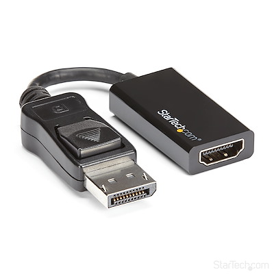
HDMI

Sometimes it is very difficult for the buyer to navigate correctly in the wide variety and the numerous versions of the HDMI cable. Which HDMI cable is better to connect various devices, I will try to tell you in a simple way in this article. Despite the fact that the HDMI interface has already firmly entered our lives, some users still ask a similar question: what is an HDMI cable for and what is hidden under this abbreviation? HDMI (High Definition Multimedia Interface) – Enables the transmission of high definition digital video and multi-channel digital audio protected against copying.

It must be said that HDMI has several important advantages over DVI digital video interface. First, the HDMI interface is smaller, and second, the interface is protected by copy protection technology. Apply HDMI cable to connect computer to monitor, TV, projector; digital video camera to a computer, TV; DVD player to TV, as well as to connect Blu-ray players, game consoles (PlayStation, Xbox) and other digital devices.

HDMI cable length. I think many of you have wondered: how long are HDMI cables? HDMI standard, the maximum cable length is ten meters. In the specification on the maximum size of the HDMI “cable” did not find information, but the length of the standard sizes can be 0.75, 0.8, 1, 1.5, 2, 2.5, 3, 5 and 10 meters. The length of the cable, which exceeds 10 meters, is not regulated by the regulations. So when deciding on the length of the HDMI cable, you don’t always have to follow the rule with a margin. For example, with a cable longer than 10 meters, signal distortion and attenuation is possible, ultimately affecting the image quality. However, the quality of the signal transmission depends not only on the size, but also on the material from which the cable is made.

For example, a standard HDMI cable (v1.4, 720 x 1080p, 75 MHz) is made of 24 AWG (0.205 mm2) oxygen-free copper and a high speed cable (v1.4, 1080 x 2160p, 340 MHz) ) is made of 28 AWG (0.081mm per square) copper.

These figures indicate that the quality of the data transmission is highly dependent on the material from which the conductors are made. It should be noted that if the HDMI cable of the “Standard” category is manufactured with high quality, then it is capable of transmitting a signal of up to 15 meters within the limits of its type. If the cable length exceeds 15 meters or after connecting digital devices there will be a loss of image quality, it is recommended to use signal amplifiers.

As you can imagine, the task of a high definition cable is to transmit all the necessary information from the source to the receiver without signal distortion. According to some manufacturers, an HDMI cable that contains expensive metals has a higher data transfer rate and less interference. However, the presence of expensive metals and the quality of the workmanship in general affect the final cost.

Therefore, when choosing an HDMI cable, you must proceed from the obligations that are assigned to you in order to save a certain amount of money. If you plan to transfer data by cable from devices (DVD, satellite receiver), where the flow of information is not great, then a cheap HDMI cable is enough for you. But to view volumetric (3D) video, where the flow of information is very high, manufacturers recommend using an HDMI cable made of expensive, high-quality materials. It is worth buying a cable made of expensive metals or not, we will analyze it in the final part of the article.

HDMI cable versions. Several well-known companies (Thomson, Philips, Hitachi, Sony, Philips, Silicon Image) were involved in the development of the HDMI interface and the result of their joint work was the first complete standard in 2002. Since then, the HDMI interface has become a hole in the digital world and has become part of our lives. As you understand, this interface is constantly evolving and with each next version the developers are improving. You can get information about the specification that this or that version of the HDMI cable was subjected to from a kind of mini-review.


Free Download Mp4Gain
picture


Mp4Gain Main Window
picture


Mp4Gain Features
picture


Free Download Mp4Gain
picture

Image difference when connecting via VGA, DVI and HDMI

Image difference when connecting via VGA, DVI and HDMI

HDMI.

VGA, DVI, and HDMI are video interfaces for transmitting video signals from a source to an image output device. They differ in the method of transmission and signal processing, as well as in the connector.

HDMI vs. DVI vs. VGA

VGA was developed in 1987 and was intended to transmit an analog signal to cathode ray tube monitors. Ten years later, LCD monitors began to dominate the market.

Via VGA, the process of transmitting a video signal was carried out by converting a digital signal into an analog one, which was then transmitted and displayed on a CRT monitor. With the advent of LCD monitors, design has become more complex. Now it was necessary to convert the signal from digital to analog, transmit it to the LCD monitor, and convert it back to digital. It became obvious that the analog signal could be removed from the chain and in 1999 the DVI video interface appeared.

VGA, DVI, HDMI and miniHDMI
In the early 2000s, HDMI was developed. It differs from DVI in a more compact connector and in the ability to transmit digital audio signals (since 2008, DVI has also learned to transmit sound). The benefits of the new interface were obvious and, at the moment, it is advanced. Its popularity has led to the appearance of varieties such as miniHDMI and microHDMI. Their difference is only in the size of the connectors.

Are DVI and HDMI better than VGA?

The main argument in favor of digital interfaces is that the analog signal is exposed to external electromagnetic fields during transmission and this leads to its distortion. There is some truth to this, but at home there is no serious interference that can cause noticeable distortion, even when transmitting over long distances. DVI and HDMI are also believed to transmit the signal as accurately as possible due to post-error correction, which is not the case with VGA. This is true, but this is an advantage only with a high-quality cable of short length (up to 5 meters).

Another reason in favor of digital video interfaces is the absence of unnecessary signal conversions, from digital to analog and vice versa. It would seem that HDMI and DVI should be better than VGA in this regard. In practice, it sometimes turns out the other way around, since in no case can you do without transformations. Digital signals are encrypted and must be decoded and processed before being displayed on the screen. For this process, separate modules of the image output devices are responsible and their transcoding algorithms are not always ideal. It is true that over time they are improving and are currently at a good level even on cheap monitors and televisions.

VGA, DVI and HDMI connectors
Cable quality is another sticking point. The analog signal is less demanding, while the digital signal needs a good conductor. This is especially true with a cable length of more than five meters. In this case, with a bit loss, the error correction does not always work and in the output we can obtain an image many times worse than if a VGA connection were used.

summarizing
Although I have downplayed the merits of DVI / HDMI, in some cases the image transmitted through them will be better. But you can only notice this if you have a high-quality cable, a reliable connection between the connectors, and a good output device – a monitor or high-definition television.

If your monitor offers a good image via VGA, don’t expect that when connected via a digital video interface the image will shine in new colors. In my practice, I have seen a significant improvement only once when connecting monitors from the company “AOC”. They worked disgustingly via VGA – the picture was blurry, fuzzy. In this case, it’s just the manufacturer’s fault.

Sound compression using software

Sound compression using software

Sound Compression

There are many types of compressors, as well as other sound processing units: digital and analog, hardware and software, manual and automatic, optoelectronic, valve, transistor, etc.

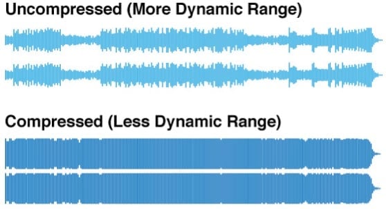
Music Loudness War: Alternative Sound Compression

Any compressor has 5 main parameters:

– Threshold level. Expressed in decibels. This is the value above which the compressor begins to attenuate the signal.How a sound compressor works
Figure: 12. The principle of operation of the sound compressor.
Choosing the right threshold is the most difficult task. When set at a high level, the signal will be virtually uncompressed, and at a low threshold level, the signal will be damped and lose its information content.

–Compression ratio (ratio). Expressed in “x: 1” format. This value determines the degree of attenuation of the signal, the level of which has exceeded the threshold value. For example, if the ratio is 1: 1, the signal is not compressed. If the value is set to ∞: 1, then the signal is severely limited and the compressor performs the functions of another device, the limiter (English Limit – to limit). The amplitude of the compressor output signal when the threshold value is exceeded can be determined by the formula:
OUT = Threshold + (IN – Threshold) / Ratio

For example, if the input signal is IN = -4 dB, the threshold is set to -12 dB, and the compression ratio is 2: 1, then the output level is OUT = -8 dB.

– Attack time. It is usually expressed in milliseconds. This value defines the time interval between the signal exceeding the threshold value and when the compressor is activated.An example of an acoustic compressor application

– Recovery (release) time. It is usually expressed in milliseconds. This value determines the time interval during which, when the level of the input signal falls below the threshold value, its compression continues. Simply put, if the attack time determines the aggressiveness and responsiveness of the compressor, then the decay time is the inertia of the compression process.

By combining attack and recovery time settings, you can achieve a wide variety of results. For example, a long attack time allows compression without affecting fast transients. Most of the time, for natural reproduction, the release time is set according to the duration of the musical instrument. Some compressors do not allow manual adjustment of the attack and release times, but set them automatically by analyzing the input signal. This greatly simplifies working with the device, but at the same time somewhat reduces its capabilities, especially in the field of artistic sound processing.

– Amplification or restoration of a signal (compensation gain). Expressed in decibels. This value determines the amplitude of the compressor output. The compression process inevitably leads to a decrease in amplitude. Therefore, many of these devices have an amplifier at the output, with the help of which the so-called normalization of the signal is carried out, that is, bringing its amplitude to the value that the input signal had. In addition, normalization simplifies the work of the sound engineer, since the signals at the input and output of the compressor are of equal amplitude when listening.
Most modern compressors offer additional modes, settings and functions:

–Bypass (bypass). When this function is enabled, the input signal goes directly to the output without undergoing any processing. This allows you to effectively compare “clean” and processed signals, make adjustments to the compressor settings.
Sensitivity adjustment. This adjustment is usually done with a level switch and allows the compressor to handle signals with an amplitude of -10.0 or +4 dB.

Type of compression (knee). Distinguish between soft compression (soft knee) and hard compression (hard knee). The differences are in how quickly and smoothly the compressor will switch from “idle” to compression mode after the signal exceeds the threshold. Examples of acoustic characteristics for soft and hard compression modes

Hard mode is used to “limit” the peaks. The sound due to the “pronounced” break in the pitch characteristic is sharp and abrupt, especially at a high compression level. With a smooth response, compression starts early when the signal level approaches a predetermined threshold. The compression ratio increases smoothly and reaches the set value at the point corresponding to the threshold value. “Smooth” compression is preferred for most instruments and voices, as it sounds more transparent and natural.

AUDIO PROCESSING DEVICES

AUDIO PROCESSING DEVICES.

Processing Device

There is a strong belief among common people that sound processing devices can improve the quality of a professional sound reproduction system. This is true … However, this thesis should not be extrapolated to the quality of the sound that this system reproduces.

Processing Devices

When using any sound processing device, its quality, in principle, can only deteriorate. The fact is that they do not solve the problem of the sound itself at all, but allow sound engineers and sound engineers to level the harshness of the performance of vocalists and musicians, eliminate inaccuracies in the sound of musical instruments, compensate defects caused by the wrong choice of equipment and its location, and also reduce the impact on reproduction. the acoustic properties of the premises. But if, for example, a vocalist has a good command of his voice and knows how to use a microphone, then he does not need a compressor.

Initially, the processes associated with the special distortion of the reproduced signal were used only in commercial sound systems, such as telephones, radio or public address systems. They have now found wide application in music and are used to make an instrument or voice unusual or unnatural. This is done primarily to surprise the audience and increase the impact of listening to the piece.

From a scientific point of view, any audio device (a microphone, a power amplifier, or a speaker system) is also a sound processing device. Firstly, they are not ideal and change the amplitude and phase of the signals, secondly, these changes occur in different ways at different frequencies, and thirdly, non-linear distortions in them lead to the appearance of new components spectral in them. By the way, the first sound processing device was the Leslie loudspeaker, which was used in conjunction with the Hammond electric organ in the 1930s and 1940s and gave it a “growl” sound.

Parameters and classification of audio processing devices.
Sound work can be done in both digital and analog formats, or even without electroacoustic conversion. In this sense, it is necessary to decide: what is meant by sound processing device?

Therefore, we will consider software and hardware that works with audio frequency electrical signals (both in analog and digital form) in real time. Before qualitatively evaluating each of the methods of working with them, it is necessary to understand how and for what purpose the processing of audio signals is carried out.

All audio processing devices can be quite conditionally divided into 3 groups:

1.-devices that do not add additional components to the signal (audio processing units);
2.-devices that add additional components to the signal (sound effects);
3.-devices that synthesize new signals based on the characteristics of the original signal (vocoders).

AUDIO PROCESSING UNITS
These include delay blocks, equalizers, crossovers, and compressors.

The need for delay units appeared in the 40s of the 20th century, when stereo sound began to be used in the cinema. As you know, a person perceives sound as a set of signals that reach each of the ears. By analyzing the delay of the sound wave reaching each ear, our brain can easily determine the location of the sound source.

Using a delay unit, used, for example, on one of the channels, it is possible to simulate a change in the position of the sound source relative to the listener. Of course, in the formation of spatial effects, the listener voluntarily participates in the sound image. In general, sound delay is a natural phenomenon associated with the fact that the speed of propagation of a sound wave is relatively low. Surely everyone is familiar with the echo effect that occurs when a wave reflects off an obstacle and passes its return path. The difference between the effect made with the help of the delay unit is that the “reflected” signal is no different from the original. Under real conditions, the spectrum of the signal during reflection changes significantly, since its various components are reflected differently from obstacles.

An example of sound propagation in a room
Currently, delay units are widely used in audio processors. They are used to equalize the sound field in large and complex rooms, in conference rooms, as well as to create sound effects such as echo, delay, reverb, etc.

COMPRESSION RULES

COMPRESSION RULES

Compression

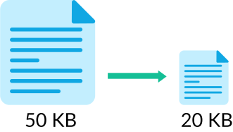
One minute of pure, uncompressed and digitized sound requires approximately 10MB on a computer’s hard drive, as a result of which, for the vast majority, music files are stored in compressed form to save space. How long does a minute of uncompressed video take? For example, to place a 60-second video with a rate of 30 frames per second, a resolution of 720×576 pixels, and a color depth of 16-bit, you will need approximately one and a half gigabytes of free disk space. And this without taking into account the audio track. After these numbers, it is probably not necessary to explain why digital video is stored on our computers exclusively in compressed form.

Compression

There are several dozen popular compression formats that use different compression algorithms, respectively giving different results.

DV (Digital Video) is one of the first compression algorithms for video transmissions, the development of which began in 1993 jointly by several companies that are the largest manufacturers of video equipment (Sony, JVC, Panasonic, Philips and Hitachi). The DV format provides a low data compression ratio (5: 1) and is characterized by a high bit rate, so the output video file is quite large. So one minute of DV video takes about 200MB (1 hour – 12GB) on digital storage media.

This format is most commonly used for compression when shooting video with consumer digital cameras and professional camcorders. At the same time, due to the small compression ratio, the footage is obtained in very high quality and the compression procedure itself, which occurs in real time, does not require powerful technical components.

It is true that it is still inconvenient to store video on a home computer, and even more so on optical discs in DV format, as it takes up too much space. So the specialists had to think of additional compression algorithms, with the help of which it would be possible to reduce the size of a digital film several times more.

MPEG (Moving Picture Experts Group) is a complete family of digital information compression standards, developed and standardized by the group of experts of the same name, formed by the ISO organization in 1988.

The first fruit of its creation was the original MPEG-1 video and audio compression standard, and in 1993, with the involvement of JVC and Philips, its Video CD (VCD) specification was developed, which is known to many users. As the name suggests, VCD is a format for storing compressed video with normal CD audio.

The use of MPEG-1 algorithms for encoding allows you to receive a video stream of up to 1.5 Mbit per second with a frame resolution of 352×288 pixels for PAL or 352×240 for NTSC, after which a normal CD can store 74 minutes of video with VHS quality sound (like a normal VCR) …

In 1995, the most popular MPEG-2 standard was released, which later became widespread in digital video DVDs, as well as in the transmission of cable and satellite television signals. The image quality here is much higher than its predecessor: at 25 frames per second, the resolution is 720×576 pixels for the PAL system and for the NTSC system: 720×480 at 30 frames / s. At the same time, the average maximum transmission width is 9.8 Mbps, which is almost 7 times that of Video CD. Another indisputable advantage of MPEG-2 is the ability to store a five-channel audio track (Dolby Digital 5.1 and DTS).

The maximum capacity of a DVD double layer disc (DVD-9) is 8.5 GB, which can store up to three hours of maximum quality video. If you are offered a DVD with multiple movies at once, know that you are most likely expecting a low-quality picture like a Video CD with very low resolution and bit rate.

Together with MPEG-2, around the same time, the development of a new MPEG-3 standard began, designed to encode audio and video transmissions on high definition television with a data transfer rate of 20 to 40 Mbps. But very It soon became clear that a slightly modified version of the MPEG-2 standard can be used for these tasks, after which all further developments of MPEG-3 were discontinued and this standard is not used today.

It should be noted that quite often the term “MPEG-3” is associated with the popular MP3 audio compression technology. But this is fundamentally wrong, as its correct name is MPEG-1 Audio Layer 3.

Finally, in 1998, a new family of video compression formats appeared: MPEG-4. It was developed with the aim of improving image quality at low bit rates.

Lossy compression: Compress audio and video

Lossy compression: Compress audio and video

Lossy cmpression

High-quality digitized audio requires a large amount of disk space. Attempts to reduce file size using standard file cabinets do not yield significant gains due to the specificity of the audio data. However, it is possible to achieve a fairly significant level of compression of the audio information using special methods based on the analysis of the data structure and subsequent compression with some loss.

Lossy Compression

The real possibility of sound processing comparable in quality to existing analog examples did not appear until the late 1980s. In 1988, the International Organization for Standardization (ISO) formed the MPEG (Moving Image Experts Group) committee. , whose main task is to develop standards for the encoding of moving images, sound and their combination. During the ten years of its existence, the committee has developed a series of norms on this subject. As a result, summarizing the extensive research in this area, several specific formats were recommended for storing data, which are excellent in quality of results and data flow.

Currently, the three most common video storage standards are MPEG-1, MPEG-2, and MPEG-4. Within the first two formats, there are also formats for storing audio information: Layer-1, Layer-2 and Layer-3. These three audio formats are defined for MPEG-1 and minor extensions are used in MPEG-2. The three formats are similar to each other, but use different levels of compromise between compression and complexity. Layer-1 is the simplest level, it does not require significant compression costs, but it also provides a negligible compression ratio. Layer-3 level: the most time consuming and provides the best compression. Recently, this format has gained immense popularity. It is often called MP3. This name is associated with the extension of the audio files stored in this format.

Founded idea, in which all audio signal loss compression methods – ignore the subtle details of the original sound, which are outside of what the human ear perceives. Here several points can be highlighted.

Noise level. Sound compression is based on a simple fact: if a person is near a loud siren, they are unlikely to hear the conversation of the people who are nearby. Also, this happens not because a person pays close attention to a loud sound, but to a greater extent because the human ear actually misses out sounds that are in the same frequency range as a louder sound. This effect is called masking, it changes with the difference in volume and frequency of the sound.

The second point is the division of the audio frequency band into subbands, each of which is further processed separately. The encoding program extracts the loudest sounds in each band and uses this information to determine an acceptable noise level for that band. The best encoding programs also take into account the influence of adjacent bands. A very loud sound in one band can affect the masking effect and nearby bands.

Another point of the codification is the use of a psychoacoustic model based on the peculiarities of the human perception of sound. Compression The use of this model is based on removing obviously inaudible frequencies with more careful preservation of sounds that are clearly distinguishable by the human ear. Unfortunately, there can be no exact mathematical formulas here. The human perception of sound is a complex process, not fully understood, so the choice of compression methods is based on analyzing listening and comparing compressed sounds differently by teams of experts. But here there are practically limitless possibilities in the field of improving psychoacoustic models. Most of the existing algorithms to encode the human voice are based on the high predictability of said signal; Universal MPEG compression algorithms have tried to apply this technique with variable success.

Another compression technique is the use of so-called joint stereo. It is known that the human hearing aid can only determine the direction of the mid frequencies, the high and low sound, so to speak, separately from the source. This means that these background frequencies can be encoded into a mono signal. In addition to all this, compression uses the difference in the complexity of the flows in the channels. For example, if there is total silence on the right channel for some time, this “reserved” place is used to improve the quality of the left channel.

THE HEADPHONE SOCKET IS IN ITS LAST DAYS??

THE HEADPHONE SOCKET IS IN ITS LAST DAYS

Ficha Conector Mini Plug Stereo 3.5 Trs La Roca Envio

Over the past fifteen years, electronic devices have made a dramatic leap towards a fully digital interface. Take a look – there are practically no analog connections even in everyday life! Screens, digital communication with a printer and mouse, digital storage devices have gone digital. However, not everything has been replaced. Grab a smartphone and you will immediately find that it is practically the only thing that has not yet been replaced. An “analog hole”, literally: a headphone jack or just a jack. But his time has come.

Jack is not even an invention of the 20th century, but the 19th century. According to legend, it appeared simultaneously with large telephone exchanges in the last quarter of the 19th century. At that time there was no automatic subscriber-subscriber switch, the problem was solved by live operators, manually connecting the required channels. Later, in the mid-20th century, with the advent of portable audio equipment, the connector began to shrink: the 1/4-inch diameter was reduced to 1/8 (from 6.35 to 3.5 mm, respectively), and then to 2.5 mm. And in the digital age, it also diversified in terms of the number of contacts: instead of the usual two or three (for stereo), a fourth appeared for the microphone, in addition manufacturers began to change the location of the contacts on the pin at will. However, the main thing is that the principle of operation has remained unchanged all this time: A classic connector is a simple wired connection from a source of electrical voltage to a speaker that actually generates sound. And the further, the more criticism it provoked.

No, normal users are still quite satisfied with it. Analog audio output is simple, reliable and mechanically robust, inexpensive and, with a few caveats, versatile. But manufacturers see it differently.

Jack is too big by today’s standards. In modern electronics, even a 3.5mm jack with only three contacts seems too large (for comparison: there are 8 contacts on the Lightning connector and up to 24 on the USB-C connector). And inside there are even more problems. Since this is an analog interface, it must be protected from parasitic pickups (i.e. correctly positioned, designed and installed in the electrical circuit), otherwise the sound quality will suffer. It is relatively “stupid”: it gives almost no feedback, so a smartphone, for example, cannot learn anything about a headset connected through a connector, except for the fact that it is connected. In an age of “smart” things, in an age where designers fight for every cubic millimeter and strive for universality, such waste and anachronism are unacceptable!

The decision suggests itself and you understand what, but it was really difficult to decide on this step. Headphone sales alone are measured in billions of dollars a year. Imagine how many of them are available! And telling all these people that the jack is outdated, that with new devices they will need new headphones / earphones, you are guaranteed to have problems. But the time has come.

Over the past month, it became apparent that an attack on analog audio was in the works. Not as coordinated as we would like, but still involving electronics leaders: Independently from each other, Intel and Apple plan to replace the connector with digital interfaces. Apple is still in the rumor stage. The leaks show that the iPhone 7 / 7S, which is expected to be released this fall, lacks a jack. Instead, the Lightning port will presumably be used. Intel officially proposes to replace the jack with USB-C (which in most cases can be considered the equivalent to USB 3) and is already working on the corresponding standard, promising to present the results in the second quarter.

What does this all mean? First of all, for digital devices of model 2017 and above, users will need new headphones / earphones or at least one adapter. This means that the price of the “ears” will increase: the digital interface requires its own audio amplifier and communication chip. But this means both higher sound quality (in itself, digital-to-analog conversion directly at the point of consumption, this guarantees) and higher “intelligence” (in “smart” headphones, you can implement playback control functions more complex, from rewinding to suppressing noise; in addition, they will be able to perform fundamentally new functions, for example, monitoring the human body, which is useful for people involved in sports) and, in general, the

Vinyl myths

Vinyl myths

Vynil myths

The idea of ​​a “vinyl renaissance” arose after the first disappointments with the then imperfect digital technologies. People were taught that the sound of CDs contains only a fraction of the information about the original analog signal (which is absolutely true), and this should be offensive to the ears of true connoisseurs of music.

The Sound of Vinyl

The audiophile code says: if you want real sound, forget about the “dead number” that cuts the sound into pieces, a week warm up the amp and use solid gold connection cables. It is believed that if you digitize a disc with a frequency of several megahertz, you can preserve its “live analogy” and “sound warmth” inaccessible to CDs. For more drama, below is an audio selection of statements by famous and well-respected people on their ideas on sound and on the now-in-fashion “vinyl” theme.

Acoustics, like any other field of knowledge, has developed its own system to measure the characteristics of sound, based on the laws of physics. Audiophiles argue that you should listen to music with your ears, not with an oscilloscope. I agree that the “musicality” of the sound does not always depend directly on the technical characteristics. For example, the effect of thermionic emission in vacuum, in contrast to the movement of electrons through a semiconductor, has linear characteristics and a predictable behavior of the amplified signal. Due to saturation with uniform harmonics, the sound takes on a pronounced color tone, causing the “recognition” effect of musical instruments. Therefore, a tube amplifier, despite the worse characteristics compared to a transistor one, may subjectively sound better. With the help of modern technology, sound can not only be heard, but also seen. A direct visual comparison of the characteristics of different formats will help answer many questions.

As for the connecting cables, which are two electrical conductors, welded symmetrically at the ends, the audio-frequency alternating current moves along them equally in both directions. Since all analog and digital cables are passive conductive elements, that is, they do not have a signal amplifier, then there is no difference when connecting them in either direction.

The gramophone disc format in its current form appeared in the 50s of the last century. Thanks to the use of a new polyvinyl chloride (vinyl for short) made of plastic and fine-grained material, the rotational speed of the record was reduced from 78 to 33 rpm and the width of the track, from 0.14 to 0.055 mm. At the same time, the playback time has increased eightfold and the sound quality has increased dramatically. The name Long Play (LP) is firmly established for the new full-length format. The phonogram is preliminarily subjected to amplitude compression so that the dynamic range matches the properties of the vinyl. This process is called mastering. Then a master disc is recorded, which is a solid aluminum base to which a thin layer of nitrocellulose varnish is applied, on which a soundtrack is formed with the help of a sapphire cutter. Then, through intermediate stages, the plates are printed using high pressure at high temperature. A press die can make 500 to 1000 copies, after which the sound quality drops. Not in vain does the term “first impression” exist which, depending on the point of view, can be interpreted as a successful copy of the disc, or as an instability in the reproduction of the final result.

The nature of sound is such that the energy of the low frequencies is much greater than that of the high ones. To convince yourself of this, simply compare the magnitude of the travel of the woofer and tweeter cones. During playback, the difference in sound pressure levels at the edges of the frequency range exceeds 50 dB, which corresponds to 400 times the amplitude ratio of the lowest and highest sounds. Taking into account the short-term signal peaks, this value can reach several thousand. The record’s microscopic soundtrack isn’t capable of conveying a great dynamic range, and mastering alone isn’t enough here. The signal level at the lower limit is close to the noise of a vinyl base, whose grain structure is comparable in size to the high-frequency vibrations of the soundtrack, which can distort the sound.

To reduce the spread of amplitudes, frequency correction is applied during recording of the master disc: low frequencies are attenuated and high frequencies are amplified, the crossover point is the frequency of 1 kHz. In this case, the difference in pressure levels.

High-resolution physical and psychoacoustic analysis of digital sound

High-resolution physical and psychoacoustic analysis of digital sound

Sample Rate

“The crux of the question is:” Why constantly increase the sample rate in modern audio communication systems (spending huge amounts of money) if the thresholds of the auditory system are limited in frequency to the 20 Hz range. 20 kHz? ”

Sample Rate

The analysis of the accumulated knowledge on this subject allows us to say that this is not enough. Given the complexity of the audio signal and the properties of the auditory system, it can be argued that only an increase in the resolution of the transmission systems in all areas (temporal, spectral, spatial and dynamic) can help solve this problem. At least now it seems clear that high resolution in the time domain is the most important for sound transparency.

As you know, to convert an analog (continuous) signal into a digital (discrete) signal, you need to perform the following operations: sampling, quantization, and encoding (Figure 1). For its implementation in all digital devices (computers, recorders, players, etc.), an ADC analog-to-digital converter (ADC) is used, the block diagram of which is shown in Figure 2. According to Kotelnikov’s theorem (Nyquist) or the “sampling theorem”, to convert an analog signal with the higher frequency f? (Hz) in digital without loss of information, it is necessary that the sampling frequency, that is, the number of samples (samples per second), is not less than 2 x f? (Hz). The digital word used, the number of binary digits in which it is equal to the number of M (bits) selected, represents the instantaneous value of the input signal,

Therefore, the sampling theorem requires that the sampling frequency be chosen high enough fd> 2fb, while the signal must remain almost constant at the time of sampling. The obligation to use a low pass filter is not specified, which is installed in all ADCs, but to avoid the appearance of excessive frequencies in the spectrum in all digital devices, there is an anti-aliasing filter that cuts the signal in the frequency fd / 2.

The recording of signals in any system begins with a microphone (Figure 3), which is a band-pass filter, which already has certain phase and transient distortions, leading to dispersion and blurring of the signal in the domain of the weather. Data on these distortions are rarely given in microphone catalogs, however, a large body of studies carried out in recent years has made it possible to establish a significant difference in these parameters between dynamic and condenser microphones. For condenser microphones, attack values ​​of several microseconds were obtained, while the decay of transient processes reaches several hundred microseconds. The importance of the phase linearity of the microphones not only inside,

Then the analog signal, which is being converted to digital, is processed by a low-pass filter at the ADC (anti-aliasing filter) input. This filter also causes dispersion of the impulse characteristics of the input signal due to uneven frequency response and phase response in the pass band, the slope of the decay curves in the transition band, and the phase non-linearity.

Such distortions lead to time spreading of the input signal and mean that each instantaneous sample at the output will contain information elements from previous samples (the number of which depends on the characteristics of the filter). Since the musical signal is a rapidly changing current with short, sharp pulses, such scattering and blurring have a certain effect on auditory perception, especially for the experienced and attentive listener with a good musical ear.

Acoustic musical signals have a non-stationary ultra-fast dynamic and temporal structure, which is due to various reasons, in particular, a rapid attack on real musical instruments, the presence of a large number of ultrasonic components in the spectrum of many instruments, the appearance of short reverberation time delays in a room, etc.

Recording an actual reverb process without losing data is also extremely difficult. When a sound source emits a complex non-stationary musical signal, each microphone, installed at different points in the room, “picks up” the complex echo. Furthermore, additional incoming signals, altered in amplitude and phase due to reflections from various surfaces, lead to an exponential increase in the total energy level entering the microphone. When the signal is turned off, there is a drop in the overall level, which is usually characterized by the reverberation time.

DAC and all the most important things to know about it

DAC and all the most important things to know about it

DAC

Without a DAC, there is no music if your music files are stored digitally. You may not know how they work, but most of us use at least one digital-to-analog converter on a daily basis, better known as a DAC or DAC (digital-to-analog converter).

DAC

They are embedded in devices such as computers, tablets, smartphones. DAC is the fundamental basis for decoding familiar digital music, converting it back to an analog signal that the human ear can hear.

Any digital signal source device, be it a CD or Blu-ray player, DAB (digital radio), TV box, game console, or music player, needs a DAC to convert the sequence of ones and zeros into a analog signal before sending it. for playback.

Traditional amplifiers do not amplify and the speakers do not reproduce the digital signal and your ears cannot hear it. They only perceive sound waves. Without a DAC, your digital music collection is useless. This is a simple set of “0” and “1”, which is necessary only for the operation of digital devices. In short, DACs play an important role in digital music playback.

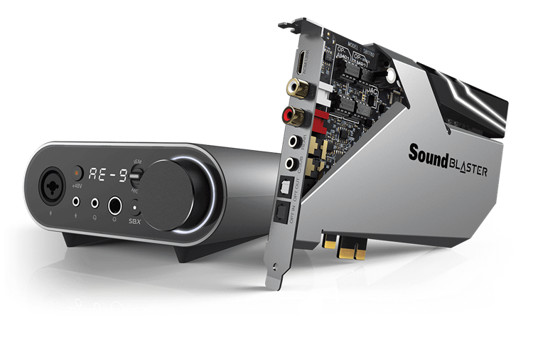
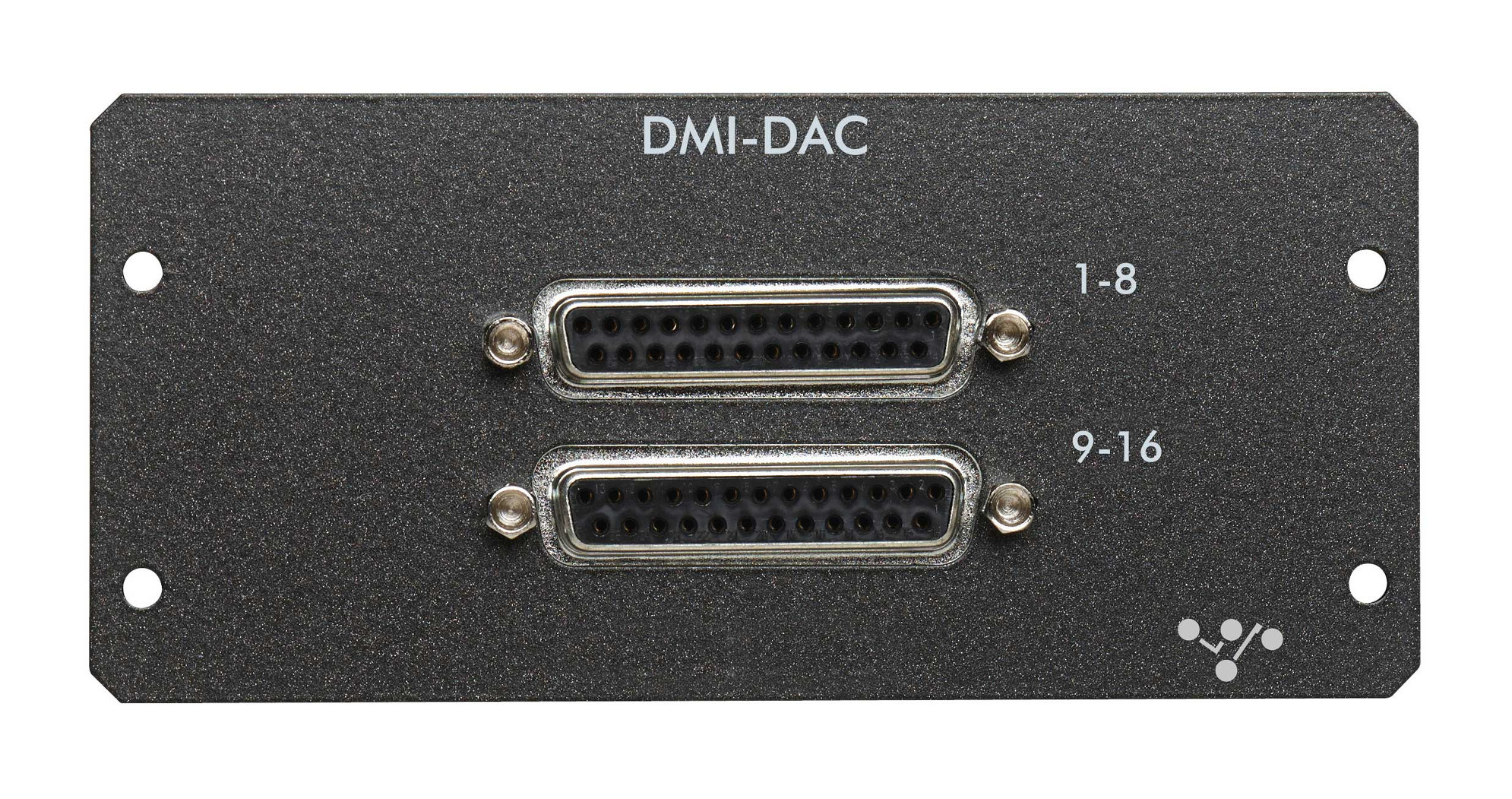
However, a serious problem is that the DAC microcircuits built into most of the devices presented above may not often be of a high enough level and cannot always provide the highest possible quality of the digital original. In this sense, the idea arises of the need to replace the DAC to transform the digital music file and make the most of its audio system.

The sounds we hear every day, whether it be music, speech, the noise of a big city or the murmur of a stream, are transmitted as sound waves and reach our ears as a continuously changing analog signal.

One of the first ways to store analog recordings was the prototypes of today’s vinyl records, and later there were tapes, but the unwanted noise during playback and the fragility of these formats demanded something new. And this innovation was the compact disc (CD), invented by Sony and Philips in the 1980s and revolutionizing the digital storage of music discs.

Digital audio is very different from analog audio. Digital music files are typically created using Pulse Code Modulation (PCM) or PCM in English, and are created by continuously measuring the amplitude of an analog signal at a constant rate.

The amplitude value is then encoded as a binary number (set of ones and zeros), and the length of this number is often called the bit depth. The time interval between measurements is determined by the sampling frequency.

With a standard CD, measurements are taken 44,100 times per second (44.1 kHz). Each measurement is recorded for storage in binary format with 16-bit precision. High-resolution audio tracks are recorded at up to 24-bit, 192 kHz or higher.

Generally speaking, digital audio data can be encoded at different bit depths and sample rates, and then into different file formats with different compression rates to reduce size. But no matter how they are created, the DAC’s job is to recognize all of this and translate it from the binary as accurately as possible to get as close as possible (as much as possible) to the analog original.

Why do I need a separate DAC?

All about DAC

In fact, almost all modern digital audio devices have a built-in DAC, but not all DACs are the same. Low-grade converters can introduce unwanted noise due to the limited capabilities of the microcircuit used. They cannot support all data rates, not to mention the added distortion due to loss of sync (jitter or jitter).

Loss of synchronization is defined as a time delay. Precise time intervals (timings) are extremely important in the process of receiving a digital music stream and if they are not maintained (usually due to poorly designed digital clock circuitry) the sound quality suffers.

Loss of synchronization problems can occur with the transmission of digital signals and are especially dangerous when transmitting a signal between two devices. Therefore, in recent years, asynchronous DACs, using their own clock source, have become widespread.

Clock generators in higher quality DACs tend to be more stable than those found in mid-range PCs, so the sound will be correspondingly better (all things being equal).