Audio conversion from digital to analog


Free Download Mp4Gain
picture

Audio conversion from digital to analog

Digital-to-Analog

How to listen to the sound after digitizing? I mean, how do you convert back from digital to analog?

Digital to Analog

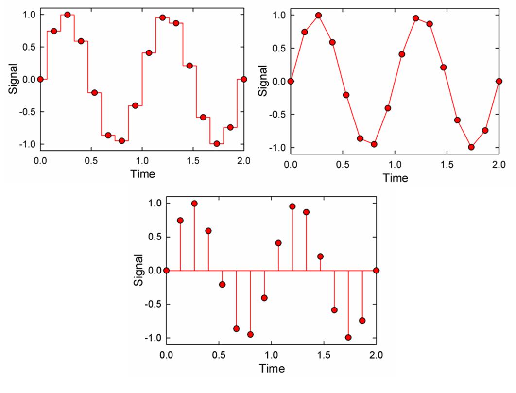
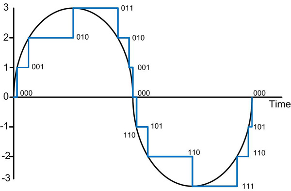
A digital-to-analog converter (DAC) is used to convert a sampled signal into an analog form suitable for processing by analog devices (amplifiers and filters) and later reproduced through acoustic systems. The conversion process is the reverse of sampling: having information about the value of the samples (signal amplitude) and taking a certain number of samples per unit of time, the original signal is restored by interpolation (Fig. 4).

More recently, sound reproduction on home computers was a problem, as computers were not equipped with special DACs. At first, the built-in PC speaker was used as the simplest sound device in the computer. Generally speaking, this speaker is still present in almost every PC, but no one remembers how to “rock” it to get it to start playing. In short, this speaker is connected to a port on the motherboard, which has two positions: 1 and 0. So if this port turns on and off quickly, then more or less credible sounds can be extracted from the speaker. The reproduction of different frequencies is achieved due to the fact that the speaker cone has a finite response and cannot instantly jump from one place to another. therefore, it “rocks smoothly” due to a sudden change in voltage across it. And if you vibrate it at different speeds, you can get air vibrations at different frequencies. The so-called Covox has become a natural alternative to dynamics: this is the simplest DAC, made on several selected resistors (or a ready-to-use microcircuit), which provides the translation of the digital representation of the signal into analog, it is that is, in actual amplitude values. The Covox is easy to make and has been a hit with hobbyists until a sound card was available to everyone. performed on several selected resistors (or a ready-to-use microcircuit), which provide the translation of the digital representation of the signal into analog, that is, into real amplitude values. The Covox is easy to make and has been a hit with hobbyists until a sound card was available to everyone. made in several selected resistors (or a ready-to-use microcircuit), which ensure the translation of the digital representation of the signal into analog, that is, into real amplitude values. The Covox is easy to make and has been a hit with hobbyists until a sound card was available to everyone.

In a modern computer, sound is reproduced and recorded using a sound card that is connected or integrated into the motherboard of the computer. The job of a sound card in a computer is audio input and output. In practice, this means that the sound card is the converter that converts analog audio to digital and vice versa. In a simplified way, the operation of a sound card can be explained as follows. Suppose an analog signal is applied to the input of the sound card and the card is turned on (by software) in record mode. First, the analog input signal goes to an analog mixer, which mixes the signals and adjusts the volume and balance. A mixer is needed, in particular, to allow the user to control the recording levels. Then the adjusted and balanced signal goes to the analog-to-digital converter, where the signal is sampled and quantized, as a result of which a stream of bits is sent to the computer via the data bus, which is the audio signal. digitized. The audio output is almost the same as the input, only in the opposite direction. The data flow directed to the sound card is overcome by a digital-to-analog converter, which forms an electrical signal from the numbers that describe the amplitude of the signal; the received analog signal can be passed through any analog path for further transformations, including playback. It should be noted that if the sound card is equipped with an interface for exchanging digital data, when working with digital audio, no analog blocks from the card are used. where the signal is sampled and quantized, as a result of which a stream of bits is sent to the computer via the data bus, which is the digitized audio signal. The audio output is almost the same as the input, only in the opposite direction.


Free Download Mp4Gain
picture


Mp4Gain Main Window
picture


Mp4Gain Features
picture


Free Download Mp4Gain
picture

How is the digital representation of signals different from analog?

How is the digital representation of signals different from analog?

analog and digital

The traditional analog representation of signals is based on the similarity (similarity) of electrical signals (changes in current and voltage) with the original signals represented by them (sound pressure, temperature, speed, etc.).

Analog vs Digital

As well as in the similarity of the forms of the electrical signals in various points of the amplification or transmission path. The shape of the electrical curve that describes (also called transfer) the original signal is as close as possible to the shape of the curve of this signal.

Such a representation is the most accurate, however, the slightest distortion of the shape of the electrical carrier signal will inevitably involve the same distortion of the shape and signal of the carrier. In terms of information theory, the amount of information in the carrier signal is exactly equal to the amount of information in the original signal, and the electrical representation does not contain redundancy that could protect the carried signal from distortion during storage, transmission. and amplification.

The digital representation of electrical signals is designed to add redundancy to avoid unwanted interference. For this, serious restrictions are imposed on the carrier electrical signal: its amplitude can take only two limit values: 0 and 1. In this case, the entire zone of possible amplitudes is divided into three zones: the lower one represents zero values, the upper , unique, and the intermediate is prohibited, inward. only interference can get in. Therefore, any interference whose amplitude is less than half the amplitude of the carrier signal does not affect the correct transmission of values ​​0 and 1. Interference with a higher amplitude also does not affect whether the duration of the interference pulse is significantly less than the duration of the information pulse.

The digital signal formed in this way can carry any useful information that is encoded in the form of a sequence of bits: zeros and ones; electrical and sound signals are a particular case of such information. Here, the amount of information in the digital carrier signal is much higher than in the original encoded signal, so the carrier signal has a certain redundancy with respect to the original, and any distortion of the waveform of the carrier signal, which still retains the receiver’s ability to correctly distinguish between zeros and ones, does not affect the reliability of the transmitted signal. by this information signal. However, in the case of exposure to significant interference, the shape of the signal can be distorted to such an extent that the precise transmission of the information being transferred becomes impossible: errors appear in it, which, with a simple coding method , the receiver can not only correct, but also detect. To further increase the resistance of a digital signal to interference and distortion, two types of digital redundancy coding are used: verification codes (EDC – Error Detection Code) and correction (ECC – Error Correction Code). ). Digital encoding is simply adding extra bits to the original information and / or converting the original bit string into a longer string and other structure. EDC allows you to simply detect the fact of an error: a distortion or loss of a useful one or the appearance of a false digit, but the information that is transferred in this case is also distorted; ECC allows you to immediately correct detected errors, keeping the information that is transferred unchanged.

Each type of EDC / ECC has its own capacity limit to detect and correct errors, after which undetected errors and distortions of the transferred information begin again. An increase in the volume of EDC / ECC relative to the volume of the original information generally increases the detection and correction capabilities of these codes.

Like EDC, the popular cyclic redundancy code CRC (Cyclic Redundancy Check), whose essence is the complex mixing of the initial information in the block and the formation of short binary words, whose bits have a strong cross-dependence on each bit of the block. Changing even one bit in a block causes a significant change in the CRC calculated from it, and the probability of such a bit distortion where the CRC does not change is extremely small even with short CRC words (a small percentage of the length of the block). The ECC uses the Hamming and Reed-Solomon codes, which also include EDC functions.

The information redundancy of the digital carrier signal leads to a significant expansion (by an order of magnitude or more) of the frequency band required for its successful transmission.