MP3 decoding algorithm.Part 2
Synchronization and error checking include header information decoding module.

After the main control module starts to work, the main control module passes the data buffer of the bit stream to the synchronization and error checking module. This module includes two functions, namely header information decoding and frame decoding Side information decoding, scale factor decoding and Huffman decoding are performed according to your information, and the obtained results are obtained after of inverse quantization, stereo decoding, alias reduction, IMDCT, frequency inversion, and synthetic polyphase filtering. of the left and right channels is then placed in the output buffer by the main control module and sent to the sound playback device (in short, it’s very complicated).
2. Main control module
The main task of the main control module is to operate the input and output buffers and to call other modules to work together. Among them, the input and output buffers are provided by the DSP control module interface.
The data in the input buffer is the original mp3 compressed data stream, and the DSP control module provides a buffer larger than the maximum possible frame length each time it is concatenated to form a new buffer.
The data stored in the output buffer is the decoded PCM data, which represents the amplitude of the sound. It consists of a fixed-length buffer. Calling the DSP control module’s interface function returns the main pointer. After the output buffer is filled, interrupt processing is called to send to the audio ADC chip (DAC stereo audio and ADC audio) connected to the I2S interface. DirectDrive headphone amplifier) to output analog sound.
3. Synchronization and error detection
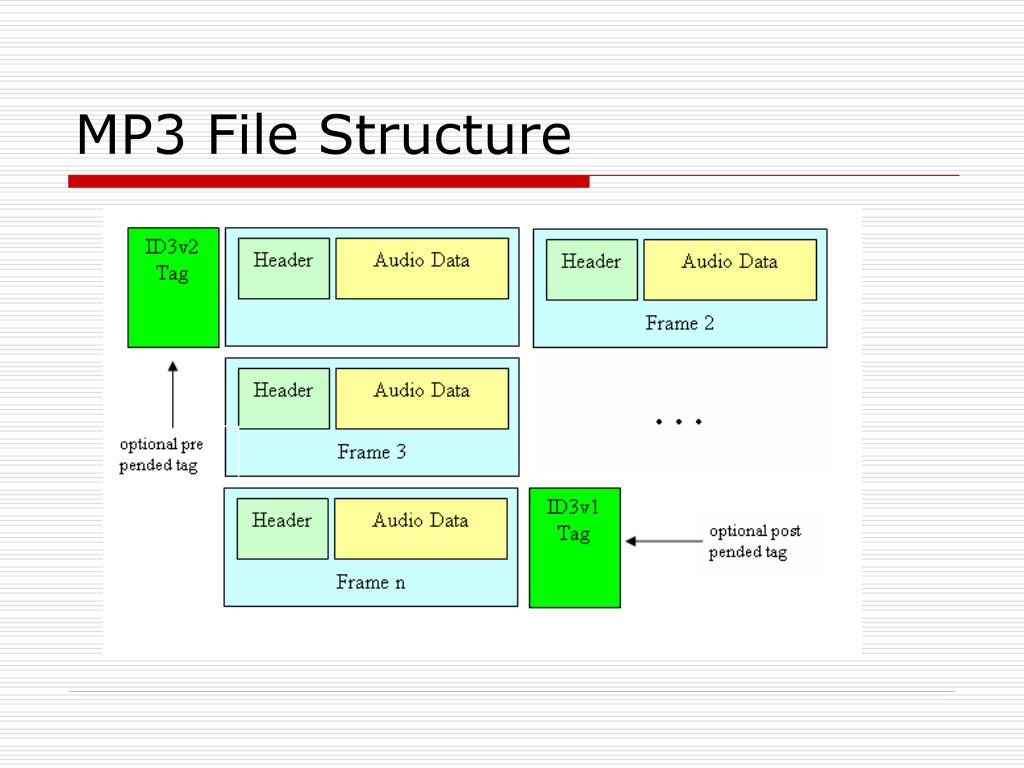
The error detection and synchronization module is mainly used to find the position of the data frame in the bit stream and decode the frame header, CRC check code and frame side information from this position, and the decoding results are used for subsequent scaling factors. Decoder module and Huffman decoder module. The main data format of the Mpeg1 layer 3 stream is shown in the following figure:
Master Data Flowchart
Among them, granule0 and granule1 represent granularity group 1 and granularity group 2 in one frame, channel0 and channel1 represent two channels in one granularity group, scalefactor is the quantized value of scale factor is the quantized Huffman encoding value , which splits into For large values and count1 1 value area
CRC check: expression is X16+X15+X2+1
3.1 Frame synchronization
The purpose of frame synchronization is to find out the position of the frame header in the bit stream. According to ISO 1172-3, the MPEG1 frame header is 12 bits “1111 1111 1111”, and the two adjacent frame headers are separated by equally spaced bytes.