Digitized sound


Free Download Mp4Gain
picture

Digitized sound

Digitized Sound

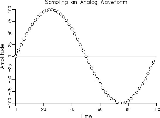
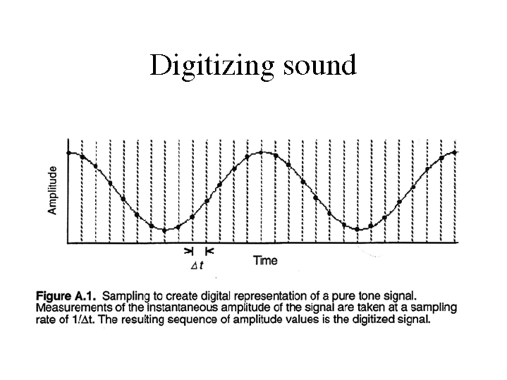
To digitize sound, it must be digitized. An analog signal is digitized by measuring instantaneous signal levels and sequentially writing these values ​​to a file. In the figure, the measured values ​​on the original curve are marked with dots.
Digitizing sound

Digitize an input analog signal

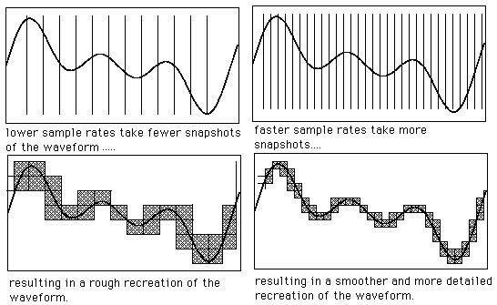
There are intervals between measurements, the duration of which is determined by the sampling frequency. The higher the sample rate, the shorter the interval and the more accurately the original waveform will be repeated. That is, the sample rate determines the acceptable frequency range of the input signal. By the Kotelnikov-Shannon theorem, it should be twice the maximum frequency of the measured signal. This is where the 44 kHz sample rate comes from. This is twice the frequency of sound that a person can hear, in theory. This is what it is: on CD. The new storage formats for digitized audio, DVD-Audio and Super AudioCD mean even higher sample rates (up to 192 kHz).

Let’s look at the image again. There is something wrong. After all, the signal from one measurement to another can change several times, which means that the sample rate is chosen much lower than required, and as a result, the signal is digitized with large distortions. The signal with the required sample rate will look like the following figure. As you can see, in this case, the difference in measurements can really be overlooked.

Another important parameter is the conversion bit depth. Determines the accuracy of the measurement of the instantaneous magnitude of the signal. The signal is measured with a step corresponding to an interval of the maximum number of intervals into which the signal is conventionally divided during the measurement. Therefore, the conversion precision is ± 1 interval. 8-, 16-, and 20-bit conversions are commonly used. (For AudioCD, the bit depth of the sound corresponds to 16 bits, for more advanced media – 20 bits). The bit depth of the conversion is determined by the sound card, that is, the ADC, with which the signal is digitized. For example, when converting an input signal with a maximum value of 100 percent with an 8-bit converter, the signal error will be 100/28 = ± 0.4 percent, and for a 16-bit conversion, 100 / 216 = ± 0.0015 percent. To clarify these dry numbers, consider the “digitizing” process in the figure. For clarity, we’ll assume our soundcard’s ADC is three-bit (how awful!). The dotted line shows the result of the input signal conversion. Consequently, the error in this case is huge: 100/23 = ± 12.5 percent. So we see that the higher the bit depth of the conversion, the more accurately the shape of the original signal is repeated.

Naturally, both with an increase in the sample rate and an increase in the conversion bit depth, the volume of the final file increases geometrically. The standards for modern sound cards are: 44 kHz sample rate and 16-bit conversion. With these settings, the file size is approximately 10MB for 1 minute of sound. This is a lot, even with modern hard drive volumes, not to mention portable devices.


Free Download Mp4Gain
picture


Mp4Gain Main Window
picture


Mp4Gain Features
picture


Free Download Mp4Gain
picture

The digitization of sound

With the diffusion of “liquid music”, knowing the processes and characteristics that characterize the transformation of sound into digital form is crucial to evaluate the formats and characteristics of audio files. In particular, when this transformation process is combined with compression and signal loss as occurs in almost all compressed formats.

digitization

… A determining factor in the fidelity of a signal is the limitation of the frequency band that it is capable of reproducing; for example, low frequencies are a problem for microphones and speakers, while high frequencies are a problem for analog circuits that set a limit on the highest frequency that can pass through them. A partial solution to these problems can be obtained by means of the numerical transformation, that is to say digital, of the waveforms that make up a sound signal.

Digitization
This does not increase the limits imposed by the reduced bandwidth determined by current transducer technology, but allows, within certain limits, the reconstruction of a clean digital signal from a deteriorated one, thus canceling aging, and above all it allows Use it countless times without increasing the noise level. But the greatest guarantee that a digital signal gives is to be able to make as many copies of it as you want and operate on it during the editing, filtering and modification phases with absolute precision without loss of quality.
So let’s look at … what happens inside a sampler. Also in this case the sound wave is received by a microphone that transduces it into an electrical signal that is sent to a low pass filter (LPF1); later it is sampled by an S&H circuit (Sample & Hold) and sent to the analog / digital converter (ADC) that transforms it into numerical values, that is, it digitizes it; a microprocessor (CPU) is responsible for storing it in memory (RAM).
During playback, the microprocessor reads the data resident in memory and sends it to a digital / analog converter (DAC) and later to a closing circuit (Sample & Hold); finally they reach a low pass filter (LPF2) and then a speaker. A digital signal is always discrete and not continuous, that is, it cannot assume the entire range of values ​​between a minimum and a maximum, values ​​that instead always identify two steps, that is, they jump without continuity between two points in space.
The activity carried out in this system is marked by a kind of internal clock (clock), which determines at what moments the system changes state, that is, at what time an event occurs that therefore cannot be in no time like common analog systems but only those dictated by the clock.
Therefore, the signal transformed into numeric cannot continuously assume all possible values, but only those that the system is capable of encoding. We will now examine again, but in more detail, the path made by the signal within a digital system. The analog signal from the microphone reaches the low pass filter (LPF1) which is used to remove all frequencies from the signal itself that are too high for the system at your disposal. Shannon’s theorem guarantees that in the sampling operation there is no loss of information if the sampling frequency Fc is at least twice the highest frequency present in the signal to be sampled.
It can also be said that the sampling frequency must be one octave higher than the highest frequency to be sampled, a frequency that does not refer to the fundamental (note that is played), but to the highest frequency present in the harmonic spectrum . At this point, the Sample & Hold circuit, in most cases included in the ADC, performs the sampling.
In practice, the system clock makes sure that every 1 / Fc second this circuit takes many pictures, taken at strictly regular intervals, called sampling periods (Tc = 1 / Fc). Of course, the more often the samples are recorded, or the better the higher the sampling frequency Fc, the more faithful the subsequent reproduction of the signal will be (Shannon’s theorem).

ALIASING
If the LPF1 low-pass filter is not placed in front of the S&H circuit, one could run into the phenomenon of aliasing or kinking, that is, the introduction of non-harmonic partials into the sample, generating noise and dissonant ring modulator effects. For example, suppose you have to sample a splash plate and you have chosen Fc = 50 kHz as the sample rate.
With these assumptions theoretically, we will be able to sample all harmonics within 25 kHz.