
ANTI-ALIASING FILTER, what is it?
An anti-aliasing filter is a low pass filter (LPF) applied to the ADC input to improve the quality of the signal sampling. If F d is the sampling frequency of the ADC, then the cutoff frequency of the anti-aliased low-pass filter is approximately equal to half 0.5 * F d. Suppressing signal frequencies above half the ADC sample rate eliminates the effect of aliasing on the signal or, as it is commonly called in the classic DSP literature, eliminates the effect of aliasing. Anti-folding filter actually provides the spectral fidelity of the ADC conversion, excluding the side tones of the signal – conversion artifacts (to use sound application terminology).

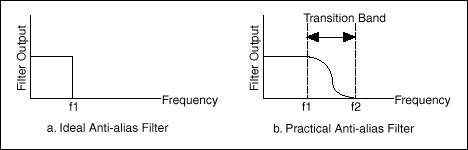
Figure 1 shows a typical frequency response (in the frequency range 0 to F d) of a high quality audio ADC. Here, the signal with the maximum possible amplitude for a given ADC input is taken as zero decibels. This frequency response is provided by a multi-stage system of digital filters in the sigma-delta ADC architecture, operating at a high modulator frequency (many times higher than F d). In combination with digital filters (if any), analog filters with a significantly lower slope of the frequency response are used to provide suppression of high frequencies in the input path of the ADC.
The ADC with anti-aliasing filter is used in sound, acoustic, vibrometry applications, in those areas where spectral conversion fidelity and maximum accuracy of AC measurements are important. In the case of the above frequency response of the converter, the highest conversion quality is guaranteed if the effective frequency band of the signal with a small margin corresponds to the frequency band 0 to 0.5 * F d. In this case, the optimum will be achieved in terms of signal-to-noise and signal-to-noise ratios, even because the mirror conversion frequencies will be suppressed (if suppression of frequencies above F d is provided).
In vibrometry, where phase delays are measured, an additional requirement of linearity of the phase frequency response is imposed on the entire ADC conversion path, including the anti-aliasing filter.
In the system of linear terms – non-linear effects of the measurement path, it can be argued that the anti-aliasing filter drastically reduces the influence of the non-linear effects of the ADC sampling operation, making the sampling operation a transformation. almost linear (if we do not take into account possible non-linearity factors of different nature, eg possible non-linearity in the ADC quantization levels).
However, it cannot be argued that the presence of an anti-aliasing filter in the ADC conversion path is acceptable for all physical signal digitization tasks. For example, a special strobe operating mode is only possible for an ADC without an anti-aliasing filter (for example, a SAR ADC), for which the upper passband frequency is significantly higher than half the frequency of sampling. Another example: when digitizing pulsed signals with fast drops with a signal spectrum width that exceeds the bandwidth of an ADC with an anti-aliasing filter, a prolonged oscillatory nature of the filter response to fast signal drops is possible, and such reactions will not be acceptable for all problems that are solved.
For a correct interpretation of the term, consider:
In the technical literature, there is also a physically similar antialiasing term, used in the field of image processing, but in measurement issues (when processing signals) it is more correct to use the term antialiasing filter used in GOST R 8.714-2010 and GOST R ISO 13373-2-2009.
In the technical literature on built-in sigma-delta ADCs, an anti-aliasing filter is often referred to as an external high-frequency analog low-pass filter, while these built-in ADCs often provide a pronounced anti-aliasing frequency response in the zones low frequency.
In the manuals of the ADC 2 modules, if it is said about the presence of an anti-aliasing filter, then it is implied that the module has a corresponding anti-aliasing frequency response, which is provided by the frequency response of the entire measurement path of the module, taking into account the frequency response of its analog path, integral ADCs, digital filters on the ADC module (for example, on FPGAs), and filters at the “higher” software level, if included in the supplied software.
We also mention possible implementations of external anti-aliasing filters in relation to AD modules

