Basic principles to reduce Redundant video data in the MPEG encoding process.


Free Download Mp4Gain
picture

Basic principles to reduce
Redundant video data in the MPEG encoding process.

MPEG video

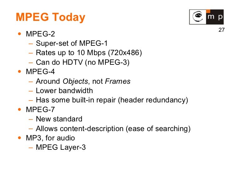
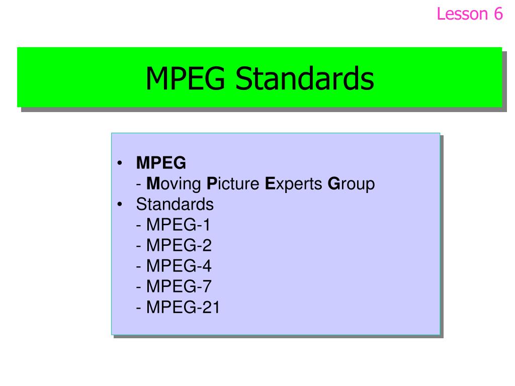
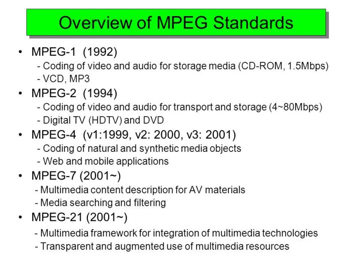
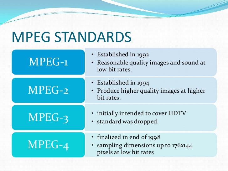
Evolution of digital video compression standards

Mpeg video format

The MPEG encoding process removes redundant video data in a series of adjacent frames.

Two adjacent frames often contain many of the same picture elements. The information in them differs in a small part from all the information contained in the frame. The video is compressed, in which not all the data from each video frame is used, but the frame dynamics changes, since in most consecutive frames of a video clip the background hardly changes, and clearly noticeable changes occur in the foreground. .

For example, there is a smooth movement of a small object against the background of an unchanging background. In this case, the complete information about the image is stored for the reference images only. For the rest of the frames, only the difference information is digitized: on the position of the object, the direction and magnitude of its displacement, on new background elements that open behind the object as it moves. In addition, this difference information is calculated not only in comparison with the previous images, but also with the later ones (since it is in them, as the object moves, that the previously hidden part of the background is revealed).

The data reduction process is as follows. First, a keyframe (I, Intra frame) is created.

The reference I-frames are used to restore the remaining frames and are placed sequentially every 10-15 frames. Only a few fragments of frames that are between I-frames have time to change, and it is these changes that are recorded during the compression process.

In addition to I-frames, two other types of frames are distinguished in MPEG:

predictable frames (P, Predicted) containing the difference between the current image and the previous I-frame or taking into account the displacements of individual fragments;
Bidirectional predictive frames (B, bidirectionally predictive), containing only references to before or after frames of type I or P, taking into account the offsets of the individual fragments.
I-frames form the basis of an MPEG stream and, through them, random access to a piece of video is performed. The I-frames are slightly compressed to ensure high visual quality.

The P-frames are encoded relative to the previous frames (I or P) and are used as a comparison pattern for an additional sequence of P-frames. In this case, a high level of compression is achieved.

B-frames are highly compressed. To link B-frames to a video sequence, it is necessary to use not only the previous image, but also the next one. B-frames are never used for comparison.

The I, P, B frames are combined into groups (GOP-Group Of Pictures), which represent the minimum repeated set of consecutive frames, for example:

(I0 B1 B2 P3 B4 B5 P6 B7 B8 P9 B10 B11) (I12 B13 B14 P15 B16 B17 P18 …)

Frames are made up of macroblocks, which are small fragments of an image 16 × 16 pixels in size. The MPEG encoder processor analyzes the frames and looks for identical or very close macroblocks by comparing the base and subsequent frames. As a result, only the difference data between frames, called vector motion code, is saved. Macroblocks that do not contain changes are ignored and therefore the amount of data to be transferred is significantly reduced. To reduce the impact of errors during data transmission, sequential macroblocks are combined into independent sections (slices). In turn, each macroblock consists of six blocks, four of which carry information on luminance (Y) and the remaining 2 blocks carry information on color difference signals (U / V). Blocks are basic units

Block diagrams are used 4: 2: 0 or for studio quality (broadcast) 4: 2: 2.

This is an important point that requires a more detailed explanation:

It is useful to know that RGB color data received from a video camera can be represented equivalently as the sum of the luminance signal (Y) and two color difference signals (U and V), called chromatic. The luminance signal Y determines the luminance of the point. The U and V color difference signals, together with the Y signal, can fully restore the original RGB data.

And it is calculated from RGB data using the formula: Y = 0.299R + 0.587G + 0.114B

The U and V signals are calculated as follows: U = R – Y and V = B – Y


Free Download Mp4Gain
picture


Mp4Gain Main Window
picture


Mp4Gain Features
picture


Free Download Mp4Gain
picture

History and characteristics of the MPEG standards. Part 5

History and characteristics of the MPEG standards. Part 5

mpeg

ABR: mechanism

Mpeg

Suppose user specified ABR mode and a certain bitrate B (user can specify absolutely any bitrate from 32 to 320, even not from standard bitrate grid, for example you can specify 129 as the rate Average Bit Rate). The encoder accepts a piece of audio (frame) to be encoded. In the same way, as in CBR, it determines its complexity (we will talk about this later). If the passage is complex, then the encoder also takes more bits for it, but not from the repository (as in CBR), but simply increasing the bitrate by the required number of steps (the selected bitrate must be included in the standard grid), thus creating a “virtual repository” (you can increase the bitrate here, this is not CBR). What does “virtual reservoir” mean? It’s simple: we assume that the user-specified bit rate B is not sufficient for the encoder, standard N bit rate, where: N> = K (we call this choice of bit rate “virtual deposit”). Then there is a K-bit encoding of the taken piece of audio. However, N> = K, that is, we use fewer bits than there are in the taken frame, so won’t we throw away these extra bits? It is these extra bits that we write to the actual deposit. Since ABR has the ability to use a “virtual reservoir”, it makes no sense to build a standard reservoir, so when the next piece of audio arrives, the bits from the reservoir will be used to encode it first, and then the encoder will decide what rate bit is needed next. In other words, if in CBR the encoder always tries to accumulate as many bits in the reservoir as possible, then in ABR the encoder, on the contrary, tries to get rid of the bits in the reservoir,

Simple passages are encoded with fewer bits, they take about 95% of the specified bit rate B, but now the rest is not deposited into the repository, the encoder just takes a frame with a lower bit rate. The resulting difference (the remaining bits) is written to the standard repository (don’t discard the remaining bits …). Example. Let’s say a “simple” passage has arrived. Then the encoder takes all the bits (if any) in the repository (present), then looks for the standard bitrate closest to which the total number of bits obtained for this frame (all the bits in the repository + rate of bits taken) is 95% of the user-specified bitrate B performs the encoding and the extra bits (if any) are stored back in the repository.

APR: Summary

So using a tank in ABR is different from CBR. In CBR, the bit rate cannot be changed, and the repository is specially saved by storing there the bits that were left (were saved) from the frame encoding at an initially fixed bit rate determined during a single pass; if bits are required for encoding and the repository is empty, then it is empty, nothing can be done about it, and encoding is simply done at the specified bit rate to the detriment of quality. In ABR, the bit rate is variable and the standard deposit is not really necessary, however, since the increase (decrease) of the bit rate necessarily occurs up to a certain table values ​​that can turn out to be higher than the number. of bits required by the encoder, then the extra bits, of course, are not discarded, but are stored in the repository. In other words, in CBR the accumulation of the standard pool is the main task, while in ABR there is an unlimited “virtual pool” and the standard is used only to store additional bits formed as a result of the difference between the table values. Bitrate and actually required bitrate.

Vbr

VBR: variable bit rate. The user indicates the desired quality. Lame, based on his psychoacoustic model, assigns to each frame exactly the number of bits necessary to achieve a certain quality. In the output stream, the frames have respectively different bit rates (which always fit into the standard bit rate table). Warehouse usage in VBR is absolutely identical to ABR, only unused frame queues go there.

Methods for estimating signal complexity

So the main difference between CBR, ABR and VBR, as you probably already understood from the above, is the use of different methods to calculate the number of bits needed to encode each frame.

History and characteristics of the MPEG standards. Part 4

History and characteristics of the MPEG standards. Part 4

MPEG Standards

What are the differences between CBR, VBR and ABR modes? (applied to the Lame encoder)

mpeg

Before starting the conversation, let’s clarify two details:

1. MP3 encoding occurs block by block: the encoded file is divided into frames (frames) with the same interval, each frame is encoded and written to the output stream; therefore, the output stream also has a frame structure.

2. Frames cannot be encoded at any bit rate, but only at one of the standard MPEG1 Layer III bit rates listed in the table: 32, 40, 48, 56, 64, 80, 96, 112, 128, 160, 192, 224, 256, 320. The standard does not provide encoding at any intermediate bit rate (“free format”).

Introduction

People using VBR in Lame generally argue this with the phrase, “I want to get constant quality, not constant bitrate. In fact, in music there are simple passages, for which 128 Kbps is enough (for example, pauses between songs), and there are also complex passages, in which a person with good hearing, a good audio card and other audio equipment. audio will hear compression. defects even at 320 Kbps / sec. In fact, such an argument is not entirely valid.

CBR

Even in CBR mode, the mp3 encoder can reallocate bits over time, emphasizing more or fewer bits during complex or simple passages, thus improving the overall sound quality. This bit reassignment is done through the so-called bit deposit: during the encoding of simple passages, the encoder spends not the entire user-specified bit rate on them, but only about 90%, about 10% is Store in bin to code difficult spots (bin is empty initially). When encoding complex passages, the encoder will use all 100% of the specified bit rate and add extra bits from the bucket (if any, that is, if the bucket is not empty). Unfortunately, according to the standard, the size of the tank is limited. This means that if a single signal lasts long enough, the tank builds its volume up to certain maximum allowed limits, and then the encoding continues using all 100% bit rate. And the opposite situation: if a complex signal lasts long enough, all the saved bits are taken from the repository (gradually) and then encoding is done using now all 100% of the bit rate.

ABR: Explanation

One could say that the reservoir does a good job with its main function – accumulating “extra” bits during simple passages and issuing them as additional bits when encoding complex passages, if not for one “but”: it has a finite and, moreover, Very limited in size, which means that it can only be stored up to certain limits and consequently can also be removed until the tank is empty. It is to eliminate this major drawback of the tank that the ABR was developed.

The main difference between ABR and CBR is that in CBR all frames must be the same size (that is, the bit rate for all frames must be the same), but in ABR this limitation is removed, respectively, there is an opportunity to use an almost infinite tank instead of the standard, very limited in size. “virtual” reservoir. Does it look like this.

History and characteristics of the MPEG standards. Part 3

History and characteristics of the MPEG standards. Part 3

MPEG

3) The MPEG-4 standard is a special article. MPEG-4 is not just an algorithm for compressing, storing and transmitting video or audio information. MPEG-4 is a new way of presenting information, it is an object-oriented representation of multimedia data. The standard operates with objects, organizes hierarchies, classes, etc. from them, he builds scenes and controls their transfer.

MPEG


The objects can be ordinary audio or video streams, as well as synthesized audio and graphics data (voice, text, effects, sounds …). These scenes are described in a special language. We will not dwell on this standard in detail; this is a topic for a separate extensive discussion. It can only be said that as a means of audio compression in MPEG-4, a set of various audio coding standards is used: the MPEG-2 AAC algorithm, the TwinVQ algorithm, as well as HVXC (Excitation Coding) voice coding algorithms. harmonic vector) – for 2-4 Kbps bit rates and CELP (Code Excited Linear Predictive) – for 4-24 Kbps bit rates. In addition, MPEG-4 has many scalability mechanisms.

4) The MPEG-7 standard, the development of which has not yet been completed, is fundamentally different from all other MPEG standards. The standard is not being developed to establish a framework for transferring data or writing and describing data of any particular kind. The standard is intended to be descriptive, intended to regulate the characteristics of any type of data, even analog. The use of MPEG-7 is intended to be closely related to MPEG-4. MPEG-7 is scheduled for release in 2001.

For the convenience of handling compressed streams, all MPEG algorithms are designed in such a way that they allow decompression (retrieval) and playback of a stream simultaneously with its reception (download) – stream decompression “on the fly” (stream playback) . This opportunity is widely used on the Internet, where the speed of information transfer is limited, and with the use of these algorithms, it is possible to process the information at the moment it is received without waiting for the end of the transfer.

What are CBR and VBR?

As you know, the result of encoding a signal using an algorithm such as MPEG-1 Layer III (MP3) (or some other algorithms) is a bit stream with a frame (block) structure. This is due to the fact that the source stream is not encoded in its entirety, but in parts. That is, in fact, the original stream is divided into blocks of a certain fixed length, then each block (frame) is encoded individually, and the result (encoded information block) is sent to the resulting stream (either a file or a stream of data).

CBR (constant bit rate) is a method of encoding the original audio stream, in which all its blocks (frames) are encoded with the same parameters (with the same bit rate). In other words, the bitrate over the entire length (all frames) of the resulting stream is constant.

VBR (Variable Bit Rate) is a method of encoding the original audio stream, in which each separate block (frame) is encoded with its own bit rate. The choice of the optimal bit rate to encode a given frame is made by the encoder itself by analyzing the “signal complexity” in each individual frame.

History and characteristics of the MPEG standards. Part 2

History and characteristics of the MPEG standards. Part 2

MPEG Standards

2) The MPEG-2 standard was developed especially to encode TV signals from television broadcasts, therefore, we would not have stopped considering MPEG-2 if in April 1997 this set had not received a “continuation” in the form of MPEG- 2 AAC (MPEG-2 Advanced Audio Coding – Advanced Audio Coding) algorithm.

MPEG Video Standards - The Road From 1 to 21


The MPEG-2 AAC standard is a collaborative effort between the Fraunhofer Institute, Sony, NEC, and Dolby. MPEG-2 AAC is a receiver for MPEG-1 technology. There are several types of this algorithm: Homeboy AAC, AT&T a2b AAC, Liquifier AAC, Astrid / Quartex AAC, and Mayah AAC. The highest sound quality compared to MPEG-1 Layer III is provided by the two penultimate implementations. All previous versions of the AAC algorithm are not compatible with each other.

As with the standard MPEG-1 audio coding suite, the AAC algorithm is based on the analysis of psychoacoustic signals. At the same time, the AAC algorithm has many additions to its mechanism, aimed at improving the quality of the output audio signal. In particular, a different type of transformation is used, noise processing is improved, the filter bank is changed, and the way the output bit stream is recorded is improved. Furthermore, AAC allows you to store the so-called encoded audio signal in the encoded audio signal. “Watermarks”: copyright information. This information is embedded in the bit stream during encoding in such a way that it is impossible to destroy it without destroying the integrity of the audio data. This technology (under the Multimedia Protection Protocol) allows you to control the distribution of audio data (which, by the way, is an obstacle to the distribution of the algorithm itself and the files created with it). It should be noted that the AAC algorithm is not backward compatible (NBC – not backward compatible) with MPEG-1 levels, even though it is a continuation (refinement) of MPEG-1 Layer I, II, III.

MPEG-2 AAC provides three different encoding profiles: Main, LC (Low Complexity), and SSR (Scalable Sample Rate). Depending on the profile used during encoding, the encoding time and the quality of the resulting digital stream change. The main main profile provides the highest sound quality (at the slowest compression rate). This is due to the fact that the main profile includes all the mechanisms for analyzing and processing the input stream. The LC profile is simplified, which affects the sound quality of the resulting stream, greatly affects the compression rate, and more importantly, the decompression. The SSR profile is also a simplified version of the main profile.

Speaking of sound quality, we can say that the 96 Kbps AAC (main) transmission provides the same sound quality as the 128 Kbps MPEG-1 Layer III transmission. With 128 Kbps AAC compression, the sound quality is notably superior. to MPEG-1 Layer III 128 Kbps.

History and characteristics of the MPEG standards

History and characteristics of the MPEG standards.

Mpeg

MPEG stands for Moving Picture Coding Experts Group, literally Moving Picture Coding Experts Group. MPEG dates back to January 1988. More precisely, the MPEG group was created by the International Organization for Standardization (ISO) and the International Electrotechnical Commission (IEC).

MPEG

The group was formed to create standards for encoding moving images and audio information. Starting from the first meeting in May 1988, the group began to grow and became a community of high-level professionals. Typically, an MPEG meeting is attended by about 350 professionals from more than 200 companies. Meetings are held about three times a year. Most MPEG members are individual specialists employed in various scientific and academic institutions. This is from the field of history. Now about practice. To date, MPEG has developed the following standards and algorithms:

MPEG-1 (November 1992): a standard for encoding, storing, and decoding moving images and audio information;
MPEG-2 (November 1994): coding standard for digital television;
MPEG-4 – standard for multimedia applications: version 1 (October 1998) and version 2 (December 1999);
MPEG-7 is a universal standard for working with multimedia information, designed to process, filter and manage multimedia information.
In order.

1) Consider the MPEG-1 packet. This kit, according to ISO standards, includes three algorithms of various levels of complexity: Layer I, Layer II and Layer III. The general structure of the coding process is the same for all levels. Each level has its own bitstream recording format and its own decoding algorithm. MPEG algorithms are generally based on the studied properties of the perception of sound signals by the human hearing aid (ie the encoding is done using the so-called “psychoacoustic model”).

Briefly about the encoding algorithm. The input digital signal is first broken down into frequency components of the spectrum. This spectrum is then cleaned of obviously inaudible components – low-frequency noise and the highest harmonics – that is, it really gets filtered out. In the next stage, a much more complex psychoacoustic analysis of the audible frequency spectrum is performed. This is done, among other things, to identify and eliminate “masked” frequencies (frequencies that are not perceived by the hearing aid due to being dampened by other frequencies). After all these manipulations, more than half of the information is excluded from the digital audio signal. Then, depending on the level of complexity of the algorithm used, a predictability analysis of the signal can also be performed. Also, based on the combined stereo (joint stereo) fact. This means that the high and low frequencies are in fact separated and encoded in mono (the mids remain in stereo). Also, if, for example, “silence” appears on one of the channels, the “empty” space is filled with information that increases the quality of the other channel or simply does not fit before. To top it off, the ready-to-use bit stream is compressed using a simplified analog of the Huffman algorithm, which also significantly reduces the volume occupied by the stream.

The MPEG-1 kit is designed to encode digitized signals with a sampling frequency of 32, 44.1 and 48 kHz. As stated above, the MPEG-1 suite has three layers (Layer I, II and III). These levels differ in the compression ratio provided and the sound quality of the resulting transmissions. Layer I allows the storage of 44.1 kHz / 16-bit signals without significant loss of quality at a transmission rate of 384 kbps, which is 4 times gain in occupied space; Layer II provides the same quality at 194 kbps and Layer III at 128 (or 112). The Layer III gain is obvious, but the compression rate when used is the lowest (it should be noted that this limitation is no longer noticeable at modern processor speeds). In fact, Layer III allows you to compress information 10 to 12 times without any loss of quality.